1/17/18, 8'04 AM
Mutable Instruments | Anushri - Assembly instructions
Page 21 of 23
https://mutable-instruments.net/archive/anushri/build/
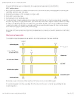
… Then screw the top and bottom case panels to them, and finish the assembly of the case with the
left, right, front and back panels.
TROUBLESHOOTING
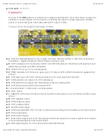
Power distribution
You can click on the image to open larger versions.
blue points
: ground (can be used as a reference point for voltage measurements).
1
: Input DC voltage, should be in the 7.5V..12V range, preferably with little ripple.
2
: Input DC voltage post protection diode - a voltage drop of a few hundred mV should be observed.
3
: Output of voltage inverter. Should be close to the voltage at point 2 in absolute value, but negative.
red points
: +5V, ±2%.
green points
: -5V, ±2%.
purple points
: +4.1V, ±1%.


