background image

Mutoh Ultima Multi-Purpose Cutting Plotter - Operation Instructions


8


AP-75125, Rev 1.3 ; 20/10/04 


Summary of Contents for Ultima 1400

Page 1: ...Multi Purpose Cutting Plotter Operation Instructions MUTOH EUROPE N V AP 75125 Rev 1 3 20 10 2004 ...

Page 2: ...2 AP 75125 Rev 1 3 20 10 04 ...

Page 3: ...of the information contained in this document the party to whom it is given assumes its custody and control and agrees to the following The information herein contained is given in confidence and any part thereof shall not be copied or reproduced without written consent of Mutoh Europe N V This document or the contents herein shall under no circumstances be used in the manufacture or reproduction ...

Page 4: ...Mutoh Ultima Multi Purpose Cutting Plotter Operation Instructions 4 AP 75125 Rev 1 3 20 10 04 ...

Page 5: ...rs in the market As a stand alone cutting plotter the Ultima can cut and plot designs onto paper as required In combination with an inkjet printer the Ultima cutting plotter is ready for contour cutting of pre printed signs made with any printer capable of printing onto cutting plotter compatible media Contour cutting is made possible via the integrated EPOS electronic positioning technology and t...

Page 6: ...Mutoh Ultima Multi Purpose Cutting Plotter Operation Instructions 6 AP 75125 Rev 1 3 20 10 04 ...

Page 7: ...NT 22 2 9 1 EPOS Alignment test plot 22 3 CUTTER CONTROLS 23 3 1 UNDERSTANDING THE OPERATION PANEL 23 3 2 DIRECT KEY ACCESS 27 3 2 1 Force selection 27 3 2 2 Speed selection 28 3 2 3 Offset selection 28 3 2 4 Tool selection 29 3 2 5 Origin selection 29 3 2 6 Test selection 30 3 2 7 Presets selection 30 3 3 CONTOUR CUTTING 34 3 4 SQUARE DETAILS 37 4 CUTTER SETTINGS SPECIAL FUNCTIONS 39 4 1 GENERAL ...

Page 8: ...Mutoh Ultima Multi Purpose Cutting Plotter Operation Instructions 8 AP 75125 Rev 1 3 20 10 04 ...

Page 9: ...ption or operation of utilities Cutters generate weak radio signals and may interfere with television reception and utilities If the cutter does interfere with radio or TV reception try the following Change the direction of your radio and TV reception antenna or feeder Change the direction of the cutter Move either the cutter or the receiving antenna so that there is more distance between them Be ...

Page 10: ...E SICHERHEITSSYMBOLE Safety Labels are attached to the internal and external area of the cutter to alert you to potentially hazardous situations or conditions The following safety labels are used in and on the cutter CAUTION When tilling or storing the media scroller always keep the fixed flange side at the bottom to avoid media from sliding down ...

Page 11: ...mended environment Temperature Room temperature 16 C to 25 C Humidity 50 to 65 non condensing Variation rate Temperature 2 C per hour Humidity 5 per hour Storage environment Temperature 0 C to 50 C Please protect your cutter from moisture dust draughts and direct sunlight It is best to keep your machine away from open windows and air conditioners See to it that there is an adequate space around th...

Page 12: ...flanges F Set of 2 water based fiber tip pens B Mutoh Ultima User s Guide G Spare cutting mat 1 pc C One knife holder with pre mounted cutting blade H Power Cord D Set of 2 spare cutting blades and 1 spring for cutting jobs 45 Offset 0 50 mm I RS 232 or USB interface cable E Blade for auto sheet off 1 pc pre installed in tool head J Quick Start Manual includes a CD rom K Test sheet verify epos ali...

Page 13: ...y two persons This to avoid back injuries Protect the plotter from firm shocks Do not dismantle the unit To unpack the cutter Step 1 Open the box Step 2 Remove the buffer box Step 3 Remove the packaging set Step 4 Take out the cutter box Step 5 Lift the cutter unit out of the box and put it on a flat and stable surface Step 6 Remove all plastic wrapping materials Step 7 Remove the pieces of foam p...

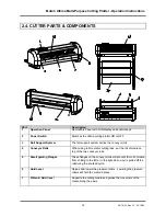
Page 14: ...onveyor rolls 4 Conveyor Rolls When using roll media for cutting jobs put the roll of media on top of the two conveyor rolls 5 Small guiding Flanges These flanges on the conveyor rolls will prevent the roll of media from shifting to the left or to the right when vinyl is pulled off the roll during the pre feed cycle 6 Hold Lever Raises and lowers the pressure rollers Lowering the pressure rollers ...

Page 15: ...nector Connector for the power cord which plugs into the main power supply of the cutter 12 Cutting head for Cutting and Sheeting Off All available tools such as knife holders drawing pens and painting pens can be secured into the head using the locking screw The tool head moves along the Y axis to locate the cutting position 13 Drive Rollers Move the cutting media along the X axis 14 Pressure Rol...

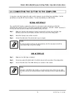
Page 16: ...both the cutter and the computer are turned off Connect one end of the serial interface cable to the serial interface connector at the rear side of the cutting plotter Step 2 Fasten the screws to secure the connector Step 3 Connect the other end of the serial cable to your computer Notes For proper operation of the serial communication it will be necessary to match the computer settings to the plo...

Page 17: ... 1 Make sure the cutter s power switch is turned OFF Step 2 Plug the plotter end of the power cable into the connector at the rear of the plotter Step 3 Plug the other end of the power cable into an electrical outlet of the correct voltage and with a proper grounding Notes The disconnect device is the plug on the power supply cord ...

Page 18: ...ounting bracket Opening this bracket will enable you to install a full range of cutting and drawing tools Step 1 Open the screw 1 to unlock the tool head mounting bracket Step 2 Hold back the clip 2 of the tool head and slide the tool into position making sure the tool collar fits into the groove just beneath the locking screw 3 Step 3 Fasten the screw to secure the tool into position ...

Page 19: ...of the cutter Step 4 Adjust the position of the pressure rollers so that they align well with the drive rollers Doing this you are helped by the tactile and audible click system for the left pressure roller The right pressure roller s movement is limited so that it can never be malpositioned Always make sure that the pressure rollers are completely inside the sheet of the media you want to load Es...

Page 20: ...e pressure rollers when the media hold lever is in the down position as this may cause damage to the system 2 8 2 Loading roll media Step 1 Put the pressure rollers in the up position and turn the power switch ON The cutter will perform its initialization routine and move the tool head to the rightmost position Step 2 Press the media select button on the operation panel and select the roll After s...

Page 21: ...t of the cutter that is not on top of a grid roller Notes Please note that the middle pressure roller should always be placed on top of a grid roller Step 5 It is best that you hold the front edge of the media in the middle with one hand and with the other hand the roll itself As you are holding the roll firmly into position pull the front edge of the media forward so that there is an even tension...

Page 22: ...e rollers are located outside your frame Step 7 Press the TEST key The display will show the following message Testplot Quality check SC 850 or SC 1400 Choose testfile Step 8 By pressing the UP or DOWN key select EPOS alignment test plot The Display on the Operation Panel will show the following message Testplot EPOS alignment test plot Choose testfile Step 9 Press the ENTER key The laser of the U...

Page 23: ... key to go to the previous menu setting Press the EXIT key if you do not want to process the changes in the cutting settings Press the EXIT key in normal mode to perform a sheet off ENTER The ENTER key has to be pressed to confirm requested changes to the cutting settings PRESETS Pressing the PRESETS key you can choose the active user Each user has its own settings that are saved You can make user...

Page 24: ...the setting menu to change the speed Press the UP or DOWN key to change the speed Press the ENTER key to confirm the change If you do not want to change the speed press the CANCEL or EXIT key FORCE Press the FORCE key to enter the setting menu to change the force Press the UP or DOWN key to change the force Press the ENTER key to confirm the change If you do not want to change the force press the ...

Page 25: ... in a menu or a selection dialog TAKE UP SHEET ROLL By pressing this key you can select take up sheet or roll media loading system The selection can only be done when no media is loaded When media is loaded the LED s only show which type of media is loaded but cannot be changed JOGG The JOGG keys are always active the cutter being ONLINE or OFFLINE To enable the user to manually move the tool head...

Page 26: ...ur Cutting LED Blinks when executing alignment procedure Take up System LED This LED will light up if you selected the Take Up System Sheet Media LED This LED will light up if you selected Sheet Media Roll Media LED This LED will light up if you selected the Roll Media Display 4 lines 16 characters Displays the LCD display messages shows settings values and allows menu wise control ...

Page 27: ...tomatic or manual alignment procedure CONTOUR CUTTING key 7 Test Perform one of the test plots onto the Ultima TEST key 8 Presets Select an user previously saved in the Ultima cutting plotter PRESETS key 3 2 1 Force selection Tool force is the amount of downward pressure that the cutter applies on the tool To change or control the tool force please perform the instructions mentioned below Step 1 P...

Page 28: ...rformed in PAUZE as well as in READY mode Speed Actual 10 New 10 In cm s Notes Changing viewing of the value can be performed in BUSY mode Please note that the effect can only be seen after a few seconds Step 3 Press the UP or DOWN key to change the force setting Step 4 Press the ENTER key to confirm the SPEED selection Notes To cancel the changes of the parameter press the CANCEL key The display ...

Page 29: ... installed tool in the Ultima cutting plotter Step 4 Press the ENTER key to confirm the TOOL selection Notes To cancel the changes of the parameter press the CANCEL key The display will show the previous value for the parameter When you press the EXIT key the changed value will be ignored and you go back to the previous menu 3 2 5 Origin selection To change control the origin please perform the in...

Page 30: ...ll show the previous value for the parameter When you press the EXIT key the changed value will be ignored and you go back to the previous menu 3 2 6 Test selection In order to enable the user to check if the cutter is fully functional without needing a computer MUTOH has integrated demo test cuts into the Ultima cutters For more information about the test cuts please refer to the chapter Finetuni...

Page 31: ...ENTER key to confirm the selected user setting The Ultima cutting plotter will load the requested user settings Notes To cancel the changes of the parameter press the CANCEL key The display will show the previous value for the parameter When you press the EXIT key the changed value will be ignored and you go back to the previous menu 3 2 7 2 Reset Use this function to change a saved user setting t...

Page 32: ... Add To add a new user setting please follow the instructions below Step 1 Change all settings for the specific cutting job you will perform Step 2 To store all these settings press the PRESETS key Step 3 Use the UP or DOWN key to select the following display Presets Add Choose user Step 4 Press the ENTER key The Ultima cutting plotter will store all settings in a new user setting Notes To cancel ...

Page 33: ... DOWN key to select the user setting you want to delete Step 5 Press the ENTER key to confirm The Ultima cutting plotter will delete the selected user setting Notes To cancel the changes of the parameter press the CANCEL key The display will show the previous value for the parameter When you press the EXIT key the changed value will be ignored and you go back to the previous menu ...

Page 34: ...ress the CONTOUR CUTTING key Contourcutting Methods Automatic Start alignment Step 5 By using the UP and DOWN key you select manual automatic or bar code Notes Before performing an alignment X Length Y Width and Roll Direction must be inserted With these values the Ultima cutting plotter will calculate the E pos correction Step 6 Press the CONTOUR CUTTING key On the display following message will ...

Page 35: ...ength Y width and roll direction Step 13 To confirm your settings press the ENTER key Step 14 The Ultima cutting plotter will start the frame detection manual or automatic as selected in step 5 In case you selected Automatic Step 15 The Ultima cutting plotter will automatically measure the four alignments points In case you selected Manual Step 15 After pressing the ENTER key following message wil...

Page 36: ...ad toward the last alignment point On the display following message will appear Manual alignment method please select the point Step 22 Use the JOGG keys to select the fourth alignment point P4 Press the ENTER key to perform Step 23 Manual alignment is completed Notes Make sure to keep the order of the alignment points P1 P2 P4 and then P 3 In case you selected Auto Barcode Step 1 After pressing t...

Page 37: ... found below VINYL Bounding Box This Bounding Box should have a minimum thickness of 3 mm default value of this square is 5 mm thick Please leave a white edge of 20 mm in front The sensor firstly detects the white space Please note that the Bounding Box around your design s will be printed Before contour cutting the E pos technology will search for the Bounding Box and measure the position of the ...

Page 38: ...n of 10 mm Black bounding box Line thickness of 3 mm 30mm Default value 5 mm Minimum size of A4 Portrait Maximum colour contrast with media Min front margin of 10 mm max 250 mm Caution When measuring the four points of the box and the cutter establishes a distortion this means the box is not a perfect rectangle or not between the margins the cutter will beep and shows following message EPOS warnin...

Page 39: ...rameter Press the ENTER key to confirm the new setting After confirmation the display will show the previous menu Notes To cancel the changes of the parameter press the CANCEL key The display will show the previous value for the selected parameter When you press the EXIT key the changed value will be ignored and you go back to the previous menu Step 4 Press the EXIT key to go back to the previous ...

Page 40: ...key to confirm your selection The actual LANGUAGE setting will now be shown on the display Language Actual ENGLISH New ENGLISH Language Step 3 By pressing the UP or DOWN key select the appropriate language Five language settings are available English German French and Dutch Notes To cancel the changes of the Language parameter press the CANCEL or EXIT key The display will show the previous value f...

Page 41: ...neously while second menu screen appears Version window Laser ON Test Left Jog key Press all keys simultaneously after startup Laser OFF Test Right Jog key Press all keys simultaneously after startup Black White or White black detection Contour cutting Jog keys Put head approximately 2cm from the B W or W B edge Press both keys simultaneously after startup Activate Sheet off knife Origin Right Pre...

Page 42: ...Mutoh Ultima Multi Purpose Cutting Plotter Operation Instructions 42 AP 75125 Rev 1 3 20 10 04 ...
Page 43: ...fe depth is a very important parameter when it comes to making high quality outputs Always make sure that the knife blade protrudes enough but not too much out of the knife holder 1 Knife Holder 2 Vinyl 3 Backing 4 Cutting blade TO ADJUST THE KNIFE DEPTH PROCEED AS FOLLOWS STANDARD KNIFE HOLDER OPTIONAL KNIFE HOLDER WITH NONIUS Hold the body 2 in one hand and adjust the depth by using the set scre...

Page 44: ... the base part and the ring in your left hand and twist the shaft until the knife point protrudes about 0 2 mm 0 008 out of the edge of the base part Tighten the ring firmly against the base part This will prevent the cutting blade from coming loose during cutting Make a manual test cut on a small piece of media of the same type that you will be using Adjust the depth until the top layer is cut co...

Page 45: ...re adjust the offset 2 by checking real cutting results on the media you will use MUTOH helps you doing this by way of a semi automatic offset adjustment routine which has been integrated into your cutter 5 3 OFFSET EFFECT The selected Offset value is LARGER than the optimum knife offset The selected Offset value is SMALLER than the optimum knife offset In this case a square corner will be cut as ...

Page 46: ...ing with the value prior to launching the adjustment routine To perform an offset please follow the instructions mentioned below Step 1 Install a knife in the tool head Please do not forget to select knife in the menu Step 2 Install a sheet of media Step 3 Press the OFFSET key The display will show the following message Offset Actual 0 50 New 0 50 Calibration base Step 4 By pressing the UP or DOWN...

Page 47: ... and easy weeding Step 3 Use the UP or DOWN key to select the correct Offset value The LED will light up the chosen value Step 4 Press the ENTER key to confirm You have selected TEST2 Step 1 After pressing the DOWN key the cutter will cut the offset TES2 Following pattern is cut 0 55 0 54 0 53 0 52 0 51 0 50 0 49 0 48 0 47 0 46 The display will show the following message Offset 0 50 Enter select U...

Page 48: ... cutter is fully functional without needing a computer Mutoh Europe has integrated four demo test cuts into the Ultima cutters Following demo cuts are accessible by pressing the TEST key Cut test SC 850 or SC 1400 Quality check Knife offset Test Settings plot EPOS Align Tune Manual EPOS Align Tune Automatic EPOS system check sensor Test sheet verify epos alignment ...

Page 49: ...eing sent from the computer but the cutter does not react Is there a proper interface cable connected Do the interface conditions on the host computer match those set on the cutter Data is sent from the computer but errors occur on the cutter s side Are the output settings correct on the host computer and in the cutting software Do the interface conditions on the host computer match those set on t...

Page 50: ...Mutoh Ultima Multi Purpose Cutting Plotter Operation Instructions 50 AP 75125 Rev 1 3 20 10 04 ...

Page 51: ...ULTIMA CUTTING PLOTTERS MEDIA COMPATIBILITY Ultima 850 Stand Model Maximum Media width 850 Roll and Cut Sheet Maximum cutting width 630 mm Ultima 1400 Stand Model Maximum Media width 1400 Roll and Cut Sheet Maximum cutting width 1200 mm 6 2 PHYSICAL DIMENSIONS ULTIMA Ultima 850 Ultima 1400 Length 1205 1775 Width 670 670 Height 1175 1175 Weight 35 kg 45 kg ...

Page 52: ...Mutoh Ultima Multi Purpose Cutting Plotter Operation Instructions 52 AP 75125 Rev 1 3 20 10 04 ...

Reviews: