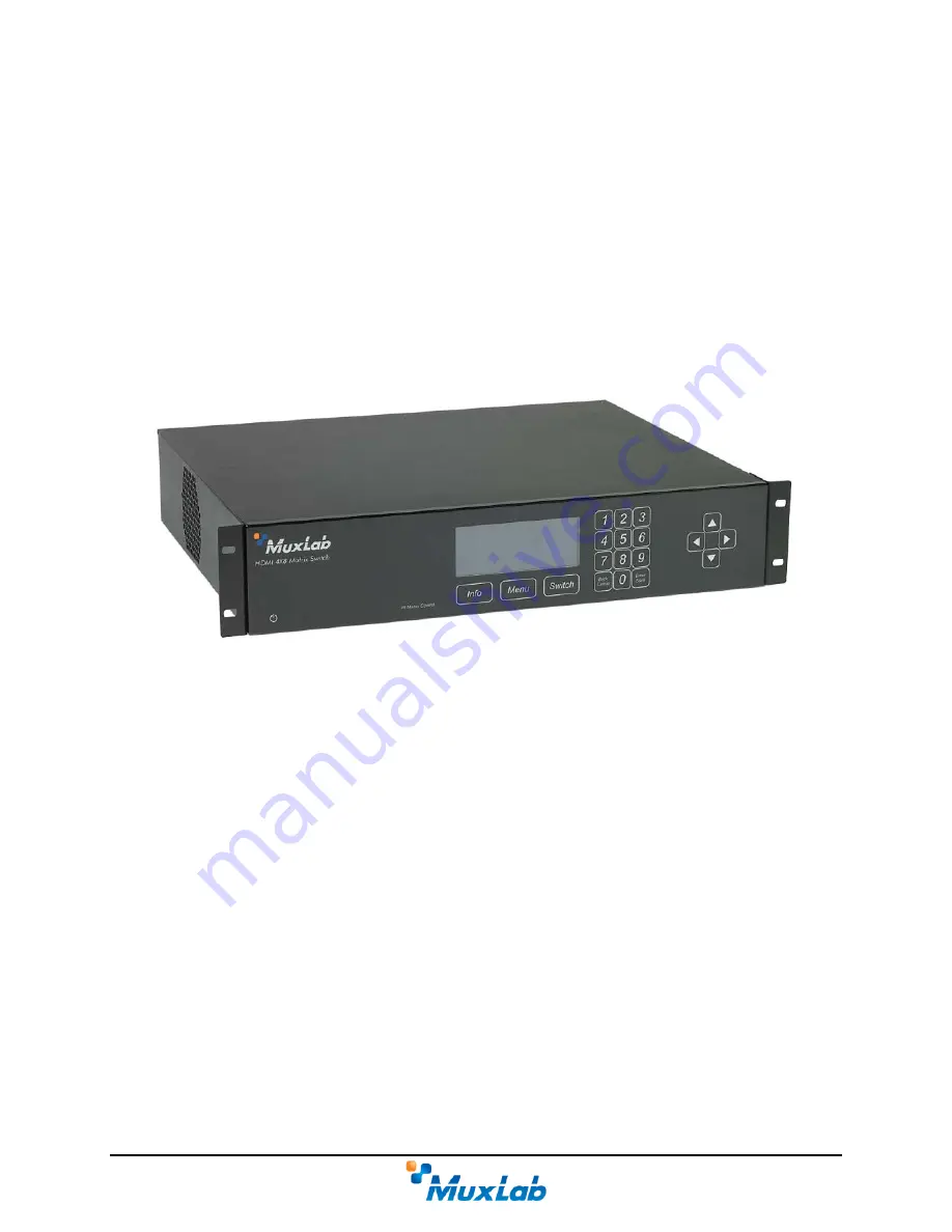
background image

HDMI 4x8 & 8x8 Matrix Switch, HDBT, PoE 

 
500418-POE-(US, UK, Euro) 
500419-POE-(US, UK, Euro) 
500468-POE-(US, UK, Euro) 
500469-POE-(US, UK, Euro) 


Installation Guide 


P/N: 94-000757-B  SE-000757-B


Summary of Contents for 500418-POE

Page 1: ...HDMI 4x8 8x8 Matrix Switch HDBT PoE 500418 POE US UK Euro 500419 POE US UK Euro 500468 POE US UK Euro 500469 POE US UK Euro Installation Guide P N 94 000757 B SE 000757 B ...

Page 2: ...an unmodified version of FreeRTOS V6 0 0 Source code available at www freertos com Printed in Canada No part of this publication may be reproduced stored in a retrieval system or transmitted in any form or by any means electronic mechanical photocopying recording or otherwise without prior written permission of the author Trademarks MuxLab is a registered trademark of MuxLab Inc Page 2 ...

Page 3: ...cklist 10 3 4 Physical Installation 11 3 5 Installation Procedure 12 3 6 Manual Control 15 3 7 Remote Control of Matrix Switch 24 3 8 Remote Control of Sources and Displays 25 3 9 EDID and DIP Switch Settings 26 3 10 Port Control Operation 27 3 11 USB Driver Setup 28 3 12 Ethernet Web Interface 31 4 Troubleshooting 41 5 Appendix 42 A ASCII Command Set 42 B IP Control Commands 55 C Infrared Remote ...

Page 4: ... pair STP cables for cost efficient connectivity Remote displays can be connected up to 230 feet 70 meters 1080p Deep Color via Cat 5e 6 UTP STP cables The Matrix Switch works in conjunction with MuxLab s HDMI Receiver 500451 RX 500454 RX or 500454 POE RX Figure 1 System Overview Applications include commercial and residential AV systems classroom projector systems digital signage boardroom system...

Page 5: ...mless integration with MuxLab s HDMI Receiver 500451 RX 500454 RX or 500454 POE RX Note The 500451 RX doesn t support RS 232 and PoE functionality HDMI input supported with resolution up to 1080p HDBaseT supported output Configurable EDID settings Web interface RS232 and USB CDC control Firmware is field upgradable Touch pad on front panel for manual control Device control over HTTP protocol 2U ra...

Page 6: ...p to 95 non condensing Dimensions 2U Rack Mountable 19 x 13 6 x 3 5 in 483 x 345 x 88 mm Accessories Included 1 IR Sensor 4 or 8 IR Emitters Remote USB Cable RS232 Cable Shipping Weight 21 6 lbs 9 8 kg Regulatory FCC CE RoHS WEEE Warranty Two 2 years Order Information 500418 POE US UPC 627699014185 HDMI 4x8 Matrix Switch HDBT 500418 POE UK UPC 627699914188 HDMI 4x8 Matrix Switch HDBT 500418 POE EU...

Page 7: ...E 500418 POE 500419 POE 500468 POE 500469 POE comes with the following parts Base unit Four 4 or Eight 8 IR Emitters One 1 IR Sensor Two 2 Brackets with screws Power Cord US EU or UK One 1 USB Type A Type B Cable One 1 RS232 Cable One 1 Infrared remote One 1 Quick Reference Sheet Please verify that all parts are present before proceeding Page 7 ...

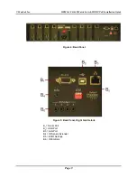
Page 8: ...tch HDBT PoE are detailed in Figure 2 and Figure 3 Please familiarize yourself with them before installing the unit Note Figures 2 to 5 illustrate the HDMI 4x8 Matrix Switch The HDMI 8x8 Matrix Switch has the same basic functionality Figure 2 Front Panel Figure 3 Front Panel Controls A1 Control Buttons A2 LED Display A3 Numeric Keypad A4 Navigational Arrows Page 8 ...

Page 9: ...HDMI 4x8 8x8 Matrix Switch HDBT PoE Installation Guide Figure 4 Back Panel Figure 5 Back Panel Right Side Details B1 Serial Port B2 USB Port B3 LAN Port B4 IR Sensor Extender B5 EDID Settings B6 IR Emitters Page 9 ...

Page 10: ... The Matrix Switch is used in conjunction with MuxLab s UTP STP HDMI Receivers 500451 RX 500454 RX or 500454 POE RX 2 The Matrix Switch is typically installed in a remote telecom room and is connected to multiple video sources and display devices via Cat 5e 6 UTP STP or HDMI cables A MuxLab Receiver is installed at each display to support the connection to the Matrix Switch via a Cat 5e 6 cable Pa...

Page 11: ...ination for the product and install the unit using standard rack mount screws Figure 6 Figure 6 Setup for Rackmount Installation For set top installation the side mounting brackets may be removed and the included rubber feet placed on the bottom of the unit When removing the mounting brackets be careful to keep and reinstall the screws on each side of the unit Figure 7 Figure 7 Setup for Set top I...

Page 12: ...t on the back panel of the Matrix Switch Using an Ethernet cable connect the Matrix Switch to the local area network Connect an RS232 cable not included between the RS232 port on the MuxLab Receiver and the RS232 port on the display Connect IR sensors and emitters as needed For more information refer to Figures 5 and 6 NOTE IR Sensor cables are equipped with a 3 5 mm stereo jack and IR Emitter cab...

Page 13: ... MuxLab Inc HDMI 4x8 8x8 Matrix Switch HDBT PoE Installation Guide Figure 8 Typical Configuration I Page 13 ...

Page 14: ... MuxLab Inc HDMI 4x8 8x8 Matrix Switch HDBT PoE Installation Guide Figure 9 Typical Configuration II Page 14 ...

Page 15: ...by using the Info Menu and Switch buttons located on the front panel just below the display as well as the numeric keypad and arrows located to the right of the display NOTE The Cancel button on the numeric keypad also returns the user to the previous screen Figure 10 illustrates the navigational layout of the manual control menu Specific menu screens depicted by boxes are described on the followi...

Page 16: ...ct name Information The information screen is reached by pressing the Info button It displays the name of the device at top followed by the IP and Mac addresses device status and firmware version Main Menu The Main Menu screen is reached by pressing the Menu button It contains four options Switch Presets Diagnostics Settings By default the Switch option is highlighted when the Main Menu screen fir...

Page 17: ...ry in the Main Menu screen and pressing the Enter Save button on the numeric keypad The Switch screen contains four options Connect a source to a display by number Connect a source to a display by name Connect all displays to a source Disconnect all displays from a source By default the top most option is highlighted when the Switch screen first displays NOTE If password protection is on pressing ...

Page 18: ...pping of connections between sources and displays or to save existing connections as a preset Diagnostic The Diagnostic screen displays four operating conditions Internal device temperature Voltage status Fans status Existence of alerts Settings The Settings screen allows the user to choose which category of settings to change Network DHCP Password RS232 Page 18 ...

Page 19: ...y Address The user navigates the Network Settings screen using the arrow keys and enters information using the numeric keypad NOTE In order to access the Network Settings screen DHCP must be disabled see below If DHCP is not disabled the following screen will appear DHCP The DHCP screen allows the user to set the state of the DHCP Dynamic Host Configuration Protocol to ON or OFF Page 19 ...

Page 20: ...as to change the password numeric characters only RS232 The RS232 screen allows the user to modify the baud rate data bits stop bit and parity settings of the device Connect Source to Displays The Connect Source to Displays screen allows the user to select which source to connect to which displays s The user selects the source and displays by their designated number Page 20 ...

Page 21: ...y their designated name Connect All Displays to The Connect All Displays to screen allows the user to connect all displays to a given source The user simply selects the source which is displayed both by number and name Disconnect All Displays from The Disconnect All Displays from screen allows the user to disconnect all displays from a given source The user simply selects the source which is displ...

Page 22: ...e user to select a preset from a list of eight options Once selected the user presses the Enter Save button on the numeric keypad The Select a Preset and Apply screen then confirms the selection Save Current Connections as The Save Current Connections as screen allows the user to save the current connection scheme to any one of eight pre existing schemes Page 22 ...

Page 23: ... Inc HDMI 4x8 8x8 Matrix Switch HDBT PoE Installation Guide Once selected the user presses the Enter Save button on the numeric keypad The Save Current Connections As screen then confirms the selection Page 23 ...

Page 24: ... at the front panel of the Matrix Switch which contains an IR sensor to receive line of sight signals from the remote An optional IR extender cable 500999 can be connected to the IR Ext port on the rear panel of the Matrix Switch The free end of the IR extender cable contains an IR sensor that can be placed up to 117 centimeters 46 inches from the Matrix Switch offering greater flexibility in usin...

Page 25: ...able 3 Matrix Switch IR Emitters Port IR Emitter Cable Sensor on Source 1 Jack End Emitter End 1 2 Jack End Emitter End 2 3 Jack End Emitter End 3 4 Jack End Emitter End 4 5 Jack End Emitter End 5 6 Jack End Emitter End 6 7 Jack End Emitter End 7 8 Jack End Emitter End 8 Table 3 Source Remote Control Configuration Using display remotes displays can be controlled at the Matrix Switch location via r...

Page 26: ...ON Figure 12 EDID DIP Switch Back Panel Various DIP switch settings enable the user to relay any display s EDID to any source Table 5 shows 8 pre defined DIP switch settings and the function of each EDID Contact 1 2 3 4 Function OFF OFF OFF OFF Variable EDID Relays EDID of display to selected source 1 OFF OFF ON OFF Fixed EDID 1080p 3D stereo 2 OFF ON OFF OFF Fixed EDID 1080p stereo 2 OFF ON ON OF...

Page 27: ... an RS 232 connection Ensure that the RS 232 cable has the straight through configuration shown in Figure 13 Figure 13 RS 232 Cable Configuration Please note that the use of USB to RS232 converter cables may result in problems depending on the quality of the converters 2 USB CDC Control Commands from an ASCII terminal may also be sent directly to the device via a USB connection Maintenance can be ...

Page 28: ...l driver download the SC 000032 A USB to serial driver file from the MuxLab website and save it to the local hard drive NOTE If the downloaded file is compressed it will have to be uncompressed before using it Plug the USB cable between the device and the PC and power up the device The Found New Hardware wizard will open Figure 14 Select Locate and install driver software recommended Figure 14 Fou...

Page 29: ...Installation Guide Figure 15 Found New Hardware Dialog Box Another dialog box will open Figure 16 Click Browse and locate the SC 000032 A USB to serial driver file downloaded earlier Once found click Next Figure 16 Browsing for Unknown Device Page 29 ...

Page 30: ... indicating that the driver software is unsigned Figure 17 Select Install this driver software anyway Figure 17 Windows Security A window will appear instructing that the software for the driver has been successfully installed Figure 18 Click Close Figure 18 Successful Installation Dialog Box Page 30 ...

Page 31: ...ow LED will blink if Ethernet activity is detected Once the Matrix Switch has been physically connected to an Ethernet network go to http AAA BBB CCC DDD where AAA BBB CCC DDD is the device IP address NOTE The device IP address can be obtained by pressing the Info button on the front panel The Login screen is the first screen to appear Figure 19 Figure 19 Ethernet Web Interface Login Screen The de...

Page 32: ...dicator to display different statuses depending on various device conditions internal temperature fan speed etc This configuration is performed in the Alarm tab of the Setup submenu After logging in the main screen appears Figure 20 It contains three submenus 1 Port Management 2 Setup 3 Help 1 Port Management The Port Management submenu Figure 20 appears after the user has successfully logged in F...

Page 33: ...place Once all selections have been made the user clicks on the Connect button to apply those selections Presets are pre established connection configurations that are used to apply wholesale mapping instructions between all displays and sources see Figure 21 The user can load any one of eight presets to the device Once a preset is selected from the Preset drop down menu the user clicks on Load Pr...

Page 34: ... connections Modify alarm settings Upgrade firmware Figure 22 Setup Submenu Port Names Tab In the Port Names tab the user can modify port names in the Display Names and Source Names columns and then click on Save to save these modifications The user can also modify the name of the entire device by changing the text that appears in the Unit Name box and clicking on Save The length of all names is l...

Page 35: ...n Save to save these modifications The length of preset names is limited to 20 characters each In the Network tab Figure 24 the user can modify network settings and passwords for users and if applicable administrators Figure 24 Setup Submenu Network Tab To implement network modifications the user makes changes to the IP address Network mask or Router fields and then clicks on Save The user also ha...

Page 36: ...er Password and then clicks on the corresponding Save button Regular users can only make changes to the User Password In the RS 232 tab Figure 25 the user can modify RS 232 settings Figure 25 Setup Submenu RS 232 Tab To implement RS 232 modifications the user selects options in the drop down boxes for Baud rate Data bits Parity bits or Stop bits and then clicks on Save Page 36 ...

Page 37: ...e 26 the user can modify the settings that dictate when an alarm will be triggered Figure 26 Setup Submenu Alarms Tab Minimum and maximum temperatures are in degrees Celsius C Fan rotation is in revolutions per minute RPMs Once all modifications have been made the user clicks on Save Page 37 ...

Page 38: ...ing the firmware must be located on the PC The user clicks on Choose File to browse for the file and then installs it by clicking on Upload It is recommended before upgrading to a new firmware to do a Backup of all the data configurations such as port names presets alarms network settings etc And then Restore these data after the firmware upgrade To do so click on the Backup button and you will be...

Page 39: ...ources or apply EDID setting from any display to a given source Figure 28 Setup Submenu EDID Tab 3 Help The Help submenu Figure 29 provides the user with contact and support information Figure 29 Help Submenu In addition to three submenu screens the Ethernet web interface also provides the user with a detailed Hardware Monitor screen Figure 30 Page 39 ...

Page 40: ...MI 4x8 8x8 Matrix Switch HDBT PoE Installation Guide Figure 30 Hardware Monitor Screen This screen can be accessed by clicking on the Product status link at the top right of any Ethernet web interface screen Page 40 ...

Page 41: ...source resolution is 1080p or less No Image Verify that the display supports HDCP White Dots in image Flickering Image Choppy Sound If using an extender verify that the distance is less than 230 feet 70 meters for UTP STP Wrong Image Appears Check matrix connection Not All Display Devices Work Check that the display supports the source resolution Table 6 Troubleshooting When contacting your neares...

Page 42: ...rminal emulation program parameters are set to the following BAUD Rate 9600 Data bits 8 Stop bits 1 Parity None Flow control None It should be noted that commands are case sensitive and arguments must be separated by a single space Commands must be entered in the following way and ended with a carriage return Page 42 ...

Page 43: ...alarm f all 150 Response Minimum RPM value s for fan s applied successfully or an error message if the command failed alarm t min value max value Description Set the minimum and maximum temperatures value before an alarm is raised Arguments min vallue 0 to 150 max value 0 to 150 Example Set the minimum and maximum temperature to respectively 5 and 70 degree Celsius before an alarm is raised alarm ...

Page 44: ...1 to 8 from output port 1 to 8 to output port 1 to 8 from output port shall be inferior or equal to to output port Example Connect input 2 to outputs 1 2 and 3 connect i 2 o 1 3 Response 2 2 2 0 0 0 0 0 or an error message if the command failed connect json input port 1 input port 2 output port 8 Description Make 8 connections disconnections in one command using json format Arguments input port 1 ...

Page 45: ...0 0 or an error message if the command failed disconnect all Description Disconnect all output ports Arguments none Example Disconnect all outputs disconnect all Response 0 0 0 0 0 0 0 0 or an error message if the command failed 4 EDID edidcopy p predefined edid Description Copy the specified predefined EDID values to all input ports Arguments predefined edid 1080p3d 1080p 1080i 1080p51 1080p71 Ex...

Page 46: ...ommand failed get i Description Get the connection state of all input ports Arguments none Example Get connection state of all input ports get i Response Input 01 connected to none Input 02 connected to 01 Input 03 connected to none and so on or an error message if the command failed get json Description Get all the output connection states in json format Arguments none Example Get all output conn...

Page 47: ...he command list definition available Arguments none Example Display all the command list help Response connect connect i input port o output port Connect 1 input port to 1 output port connect i input port o all Connect 1 input port to all output port connect i input port o from output port to output port Connect 1 input port to a specific range of output port disconnect disconnect i input port Dis...

Page 48: ...d output port Arguments output port 1 to 8 name up to 20 characters Example Set the name Kitchen TV for output port 4 name o 4 Kitchen TV Response Output Names Output 1 Output 2 Output 3 Kitchen TV Output 5 Output 6 Output 7 Output 8 or an error message if the command failed name o Description Get a list of all the output port names Arguments none Example Get list of all output port names name o R...

Page 49: ...Preset 6 Week end Preset 8 or an error message if the command failed name unit name Description Set a name for the unit Arguments name up to 20 characters Example Set the name MuxLab Switch for the unit name unit MuxLab Switch Response Unit Name MuxLab Switch or an error message if the command failed name unit Description Get the unit name Arguments none Example Get the unit name name unit Respons...

Page 50: ...SK 255 255 0 0 GATEWAY 10 0 0 1 DHCP OFF or an error message if the command failed Network m mask address Description Set a specific mask address note that DHCP must be disabled to perform this action Arguments mask address Example Set the mask address to 255 255 255 0 Network m 255 255 255 0 Response IP 192 25 80 13 MASK 255 255 255 0 GATEWAY 10 0 0 1 DHCP OFF or an error message if the command f...

Page 51: ...e the web admin password to new123 password wadmin new123 Response Web server Admin password set successfully or an error message if the command failed password wuser web user password Description Set the web server User password Arguments web user password alphanumeric max length 20 Example Change the web user password to new123 password wuser new123 Response Web server User password set successf...

Page 52: ...ers Example Send the following 4 bytes to port 3 0xA1 0x55 0xF2 and 0xC8 senddata p 3 b 9600 d A155F2C8 Response 0304A1B2C3D4 Where 03 port number 04 Data length that follows max value 0x28 bytes A1B2C3D4 data in hexadecimal 0xA1 0XB2 0xC3 0xD4 Command performed successfully or an error message if the command failed 13 Serial Data serialdata o output port state Description Set output serial port s...

Page 53: ...ta bits parity stop bits Description Modify other RS 232 settings Arguments data bits 7 or 8 parity e o or n i e even odd none stop bits 1 or 2 Example Set the RS 232 settings to 8 data bits no parity and 1 stop bit serial o 8 n 1 Response Baud Rate 115200 Data bits 8 Stop bit 1 Parity NONE or an error message if the command failed serial b baud rate o data bits parity stop bits Description Modify...

Page 54: ...it status status Response Temperature 28 Celsius Voltage monitors Ok Fans Fan 1 1850 RPM Fan 2 1850 RPM or an error message if the command failed 16 Version version Description Get the current firmware version Arguments none Example Get current firmware version version Response Master firmware version 1 0 0 or an error message if the command failed Page 54 ...

Page 55: ...permitted Also null values are not permitted Use 0 instead 3 Basic Usage All read and write operations are performed via HTTP GET and HTTP POST commands respectively While you can perform a GET at any time a POST command will require prior authentication 4 Basic Authentication Authentication is performed in two simple steps 1 Obtain a Session ID Perform a GET request on var session json to obtain ...

Page 56: ...ideo connections 2 Admin Can perform any command without restriction To obtain credentials you will need to POST an array of two strings to var auth json the userlevel and the password associated to that user For example POST var auth json sid 12345 POST data 2 mypassword 4 Basic Authentication Continued If successful you will receive an HTTP 201 Created response Sessions will automatically close ...

Page 57: ...Indicate if dhcp is ON 1 or OFF 0 Example 1 var tempalarms json Array of 2 integers Contains the Min and Max temperature of the unit before an alarm is raised Example 5 70 var auth json Array of a single integer Contains an integer representing the current user level from 0 to 2 Example 2 var session json Array of a single integer Represents a new session ID Example 3847534 var logout json None De...

Page 58: ...ray of 4 integers Set the following serial port settings baud rate data bits 7 or 8 parity 0 Even 1 Odd 4 None stop bits 0 1 stop bit 2 2 stop bits Example 9600 8 4 0 var ip json Array of 4 integers Set the IP address Example 10 0 101 96 WARNING This request will actually take effect after the DHCP request will be sent var netmask json Array of 4 integers Set the mask address Example 255 255 0 0 W...

Page 59: ...1080p 5 1 5 1080p 7 1 Example to apply the predefined EDID 1080i 3 var edidcopy_o json Array of 4 or 8 integers Contains 4 or 8 items for the 4 or 8 sources Each number is the output port display number that you want to copy the EDID from and copy it to the associated source 0 means do nothing In the example below the EDID from the Display 2 will be copied to the source 3 and he EDID from the Disp...

Page 60: ...1E Display 8 1A Discreet IR Control Key Codes Outport 1 Source Select Key Code 0x80 0x81 0x82 0x83 Outport 2 Source Select Key Code 0x90 0x91 0x92 0x93 Outport 3 Source Select Key Code 0xA0 0xA1 0xA2 0xA3 Outport 4 Source Select Key Code 0xB0 0xB1 0xB2 0xB3 Outport 5 Source Select Key Code 0xC0 0xC1 0xC2 0xC3 Outport 6 Source Select Key Code 0xD0 0xD1 0xD2 0xD3 Outport 7 Source Select Key Code 0xE...

Page 61: ...mber RMA issued by its Customer Service Department and a proof of purchase date If this product is delivered to MuxLab by mail you agree to assume risk of loss or damage in transit to prepay shipping charges to the warranty service location and to use the original shipping container or equivalent THE ABOVE LIMITED WARRANTY IS THE ONLY WARRANTY COVERING YOUR MUXLAB PRODUCT THERE ARE NO OTHER WARRAN...

Page 62: ...not returned Product more than six months old including shelf life The defective unit must be returned prepaid to MuxLab and then the unit will be repaired or if repair is not possible replaced by an equivalent unit and returned to the customer within one 1 month of receiving any returned product There is no charge for repair parts and labor during the full warranty period Items Defective and not ...

Reviews: