© MuxLab Inc.
HDMI 4x8 & 8x8 Matrix Switch, HDBT, PoE Installation Guide
3.5.
Installation Procedure
In order to install the HDMI 4x8 & 8x8 Matrix Switch, HDBT,PoE, please follow the
steps below:
1.
Place the Matrix Switch in its final location (see Section 3.4 Physical Installation).
2.
Ensure that power is OFF on all sources and displays.
3.
Using HDMI cables (not included), connect each source to an
HDMI IN
port on
the back panel of the Matrix Switch.
4.
Ensure that one MuxLab Receiver is connected to each display using an HDMI
cable (not included). For more information, refer to MuxLab’s
500454 Quick
Installation Guide.
5.
Using Cat 5e/6 UTP/STP cables (not included) connect each MuxLab Receiver to
an
HDBT OUT
port on the back panel of the Matrix Switch.
6.
OPTIONAL:
•
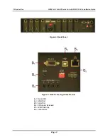
Using an RS232 or USB cable, connect a computer to the corresponding port
on the back panel of the Matrix Switch.
•
Using an Ethernet cable, connect the Matrix Switch to the local area network.
•
Connect an RS232 cable (not included) between the RS232 port on the
MuxLab Receiver and the RS232 port on the display.
•
Connect IR sensors and emitters as needed. For more information, refer to
Figures 5 and 6. NOTE: IR Sensor cables are equipped with a 3.5 mm stereo
jack, and IR Emitter cables are equipped with a 3.5 mm mono jack.
7.
Power up the MuxLab Receivers and HDMI equipment.
8.
Plug the power cord into an AC power outlet and turn on the power by using the
Power Switch located on the back of the unit. If power is present, the blue power
LED will be illuminated.
9.
Ensure that the source and appropriate display LEDs are ON. Images should
appear on the displays within 10 seconds. For signal or image quality problems,
refer to Section 4 Troubleshooting.
10.
Figures 8 and 9 show some typical configurations.
The Matrix Switch is now ready to use. See Section 3.7 Manual Control for
instructions on usage.
Page 12


