© MuxLab Inc. 2017
transmitting over the network, use an Ethernet Switch between the TX & RX unit.
5.
If the configuration is a point-to-multipoint or multipoint-to-multipoint:
5a.
You will need to use an Ethernet Switch with Gigabit ports and DHCP Server support. In
addition IGMP Protocol support is required for the multipoint-to-multipoint case.
Verify that
the Ethernet Switch is configured correctly and that the DHCP Server is enabled and
that the IGMP Protocol is enabled for multipoint-to-multipoint applications
. See the
operating manual for more information about configuring the Ethernet Switch.
5b.
Connect all Transmitters and Receivers to the Ethernet Switch.
5c.
Use the DIP Switches to select a unique Device ID for each Transmitter present on the
network and configure each Receiver Device ID to the corresponding selected Transmitter.
Note
: This step is not necessary if the MuxLab ProDigital Network Controller (500811) is used.
6.
Powering the Transmitter or Receiver via an external power supply is only necessary where PoE
(PSE) is unavailable. If PoE is unavailable, connect the 5 VDC power supply (sold separately) to
each Receiver and to an AC power outlet. Next connect each Transmitter in the same manner. If
power is present, the green power LED on each Transmitter and Receiver will illuminate.
Note: Power ‘ON’ the HDMI over IP PoE Extender only after all data connections are made.
7.
Power ‘ON’ the HDMI equipment and verify the image quality.
8.
This product supports IR pass-thru control. If infrared remote control is needed to control the
Source equipment from the Display, connect the IR Sensor (sold separately) to the 3.5mm Stereo
Jack of the Receiver and the IR Emitter (sold separately) to the 3.5mm Mono Jack of the
Transmitter.
Note: You can differentiate the IR Sensor and Emitter by looking at the 3.5 mm plug. The IR Sensor is
using a Stereo Plug (3 Contacts) and the IR Emitter a mono plug (2 Contacts).
9.
Position the IR Sensor so that it is directed at the hand-held remote control. For a clear IR signal
reception, aim the hand-held remote control at the top of the IR Sensor enclosure.
10.
Position the IR Emitter as close as possible to the source’s IR Sensor (i.e. DVD player). For a clear
IR signal reception, the IR Emitter can be glued on the source’s IR Sensor. The IR Emitter’s signal
is transmitted from the side of the enclosure.
11.
This product supports RS232 bidirectional communication. On the Transmitter, the RS232 port is
configured as a DCE; and on the Receiver as a DTE. Please connect your RS232 cable accordingly
as previously indicated. The default settings are 9600, N, 8, 1.
12.
To send an RS232 packet to a specific device, you need to put the IP address in front of the packet.
This communication is meant to be machine to machine; and hexadecimal codes must be used. For
example, to send the message “Hello” to a device having an IP address of 192.168.168.55, send the
following hexadecimal string: 0xC0 0xA8 0xA8 0x37 0x48 0x65 0x6c 0x6c 0x6f. (or “192 168 168
55 H e l l o” in hexadecimal).
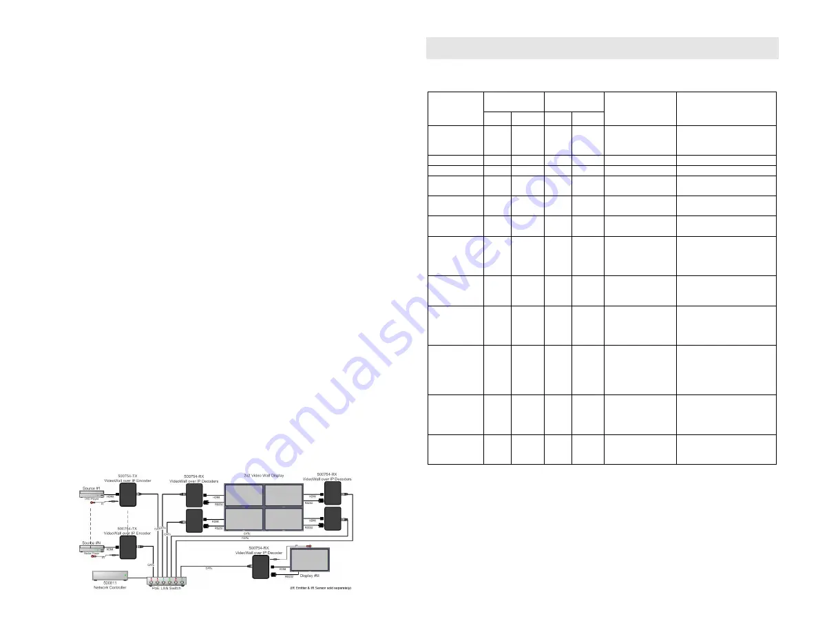
13.
To setup a video wall, please use the 500811 ProDigital Network Controller and follow the steps in
the controller manual.
14.
The following diagram illustrates a typical 2x2 Video Wall configuration.
Troubleshooting
The following table describes some of the symptoms, probable causes and possible solutions in regard to
the installation of the HDMI over IP PoE Extender:
Symptom
Transmitter
LEDs
Receiver LEDs
Probable
Cause
Possible
Solutions
Power
Link
Power
Link
No image
OFF
OFF
OFF
OFF
No power
• Check power connections.
• Check PoE Ethernet
Switch setup.
No image
ON
OFF
ON
ON
Internal error
• Reboot the Transmitter.
No image
ON
ON
ON
OFF
Internal error
• Reboot the Receiver.
No image
ON
ON
ON
ON
UTP cable
• Check the Transmitter
UTP cable.
No image
ON
BLINK
ON
ON
UTP cable
• Check the Receiver UTP
cable.
No image
ON
BLINK
ON
BLINK HDMI cable
• Check the HDMI cable
quality.
Choppy image
ON
BLINK
ON
BLINK Ethernet Switch
• For multipoint-to-
multipoint enable the
IGMP mode on the
Gigabit Ethernet Switch.
Choppy sound
ON
BLINK
ON
BLINK Synchronization
• Check cable length.
• Check the HDMI cable
quality.
Image flickers
when powering
up nearby
equipment.
ON
BLINK
ON
BLINK Interference
• Use STP cables.
IR not
functioning *
ON
BLINK
ON
BLINK Remote control not
directed to the IR
Sensor or IR
Emitter not directed
to the source.
• Make sure the IR Sensor
is directed towards the
remote and the IR Emitter
to the equipment.
IR not
functioning *
ON
BLINK
ON
BLINK Interference from
sunlight,
fluorescent, neon or
halogen lights.
• Place the IR equipment
away from the interfering
light source.
IR not
functioning *
ON
BLINK
ON
BLINK RF radiation
interference from
the TV.
• Place the IR equipment
away from the interfering
RF radiation source.
* IR Emitter and IR Sensor sold separately.
If you still cannot diagnose the problem, please call MuxLab Customer Technical Support at 877-689-
5228 (toll-free in North America) or (+1) 514-905-0588 (International).