© MuxLab Inc. 2022
3c.
If necessary, connect the Transmitter HDMI Out to a local display with an HDMI
compliant cable.
4.
To install the Receiver (such as the 500759-RX):
4a.
Connect the Receiver to the destination HDMI display with an HDMI compliant cable.
4b.
If the application is point-to-point, then connect one (1) Cat 5e/6 cable (or higher)
coming from the Transmitter to the RJ45 LINK connector on the Receiver. If
transmitting over the network, use an Ethernet Switch between Transmitter and
Receiver.
5.
If the configuration is a point-to-multipoint or multipoint-to-multipoint:
5a.
You will need to use an Ethernet Switch with Gigabit ports and DHCP Server support.
In addition, Jumbo Frame support is required, and IGMP Protocol support is required for
the multipoint-to-multipoint case.
Verify that the Ethernet Switch is configured
correctly and that the DHCP Server, IGMP Protocol, and Jumbo Frames are
enabled
. See the manufacturer operating manual for more information about
configuring the Ethernet Switch.
5b.
Connect all Transmitters and Receivers to the Ethernet Switch.
5c.
Use the DIP Switches to select a unique Device ID for each Transmitter present on the
network and configure each Receiver Device ID to the corresponding selected
Transmitter.
Note
: This step is not necessary if the MuxLab Pro Digital Network Controller
(500812) is used.
6.
Powering the Transmitter or Receiver via an external power supply is only necessary where
PoE (PSE) is unavailable. If PoE is unavailable, connect the 5 VDC power supply (sold
separately, model 500993) to each Receiver and to an AC power outlet. Next connect each
Transmitter in the same manner. If power is present, the green power LED on each
Transmitter and Receiver will illuminate.
Note: Power ‘ON’ the HDMI over IP PoE TX with Loop Out only after all connections
have been made.
7.
Power ‘ON’ the HDMI equipment and verify the image quality.
8.
This product supports IR pass-thru control. If infrared remote control is needed to control the
Source equipment from the Display, connect the IR Sensor (sold separately, model 500991) to
the 3.5mm Stereo Jack of the Receiver and the IR Emitter (sold separately, model 500990) to
the 3.5mm Mono Jack of the Transmitter.
Note: You can differentiate the IR Sensor and the IR Emitter by looking at the 3.5 mm
plug. The IR Sensor is using a Stereo Plug (3 Contacts) and the IR Emitter a
mono plug (2 Contacts).
9.
Position the IR Sensor so that it is directed at the hand-held remote control. For a clear IR
signal reception, aim the hand-held remote control at the top of the IR Sensor enclosure.
10.
Position the IR Emitter as close as possible to the source’s IR Sensor (i.e. DVD player). For a
clear IR signal reception, the IR Emitter can be glued on the source’s IR Sensor. The IR
Emitter’s signal is transmitted from the side of the enclosure.
11.
This product supports RS232 bidirectional communication. On the Transmitter, the RS232
port is configured as a DCE; and on the Receiver as a DTE. Please connect your RS232 cable
accordingly. Configure the RS232 communications setting via the device web interface.
12.
Commands or messages may be sent via RS232 by connecting a PC to the RS232 port of the
HDMI over IP PoE Extender, or over the network via IP. This communication is meant to be
machine to machine.
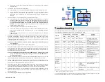
13.
The following diagram illustrates a typical application.
Cat 5e/6 Cable
HDMI Cable
500759-TX-HLO
Ethernet
Switch
500759-RX
500759-RX
500759-RX
500759-RX
500812
ROUTER
Tablet
Video Wall
HDMI Loop Out
Video Source
Local TV
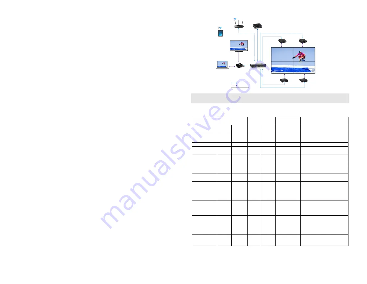
Troubleshooting
The following table describes some of the symptoms, probable causes and possible solutions in regard to
the installation of the HDMI over IP PoE TX with Loop Out, UHD-4K:
Symptom
Transmitter LEDs
Receiver LEDs
Probable
Cause
Possible
Solutions
Power
Link
Power
Link
No Image
OFF
OFF
OFF
OFF
No power
• Check power connections
• Check PoE Ethernet Switch
Setup
No Image
BLINK
OFF
BLINK
ON
Booting
• Wait until booting process finish
No Image
ON
OFF
ON
OFF
No Ethernet Link • Check Ethernet Switch Status
• Check UTP Cables
Info Screen
ON
OFF
ON
BLINK UTP Cable
• Check the Transmitter UTP
cable
Info Screen
ON
ON
ON
OFF
UTP Cable
• Check the Receiver UTP cable.
Info Screen
ON
BLINK
ON
BLINK No Data
Connection
• Check if DIP Switch settings
match
Info Screen
ON
ON
ON
BLINK Wrong setting on
Decoder
• Check DIP Switch address of the
Receiver
Choppy Video
ON
ON
ON
ON
Configuration
• Check cable length
• Check the HDMI Cable Quality
• Check if Jumbo Frame and
IGMP are enabled on the
Ethernet Switch
Image flickers
when powering
up nearby
equipment
ON
ON
ON
ON
Interference
• Use STP cables
IR not
functioning *
ON
ON
ON
ON
Interference from
sunlight,
Fluorescent,
Neon or Halogen
lights.
• Place the IR equipment away for
the interfering light
IR not
functioning *
ON
ON
ON
ON
Interference from
RF radiation
from the TV
• Place the IR equipment away for
the RF radiation
* IR Emitter and IR Sensor sold separately.
If you still cannot diagnose the problem, please call MuxLab Customer Technical Support at 877-689-
5228 (toll-free in North America) or (+1) 514-905-0588 (International).


