


Operations Manual
Page | 23
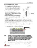
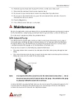
Mold Pressure Guard (MPG)
The machine features a Mold Pressure Guard (MPG),
which is used to control the maximum allowable
pressure at the mixing head. The MPG can be used to
provide line pressure control during an injection or as
a safety mechanism to prevent the line pressure from
exceeding the maximum working pressure of the
injection line to the mold.
The MPG block is supplied with 2 air lines. One air-
line supplies air from the MPG pressure regulator on
the control panel. The other is connected to an internal
circuit on the control box.
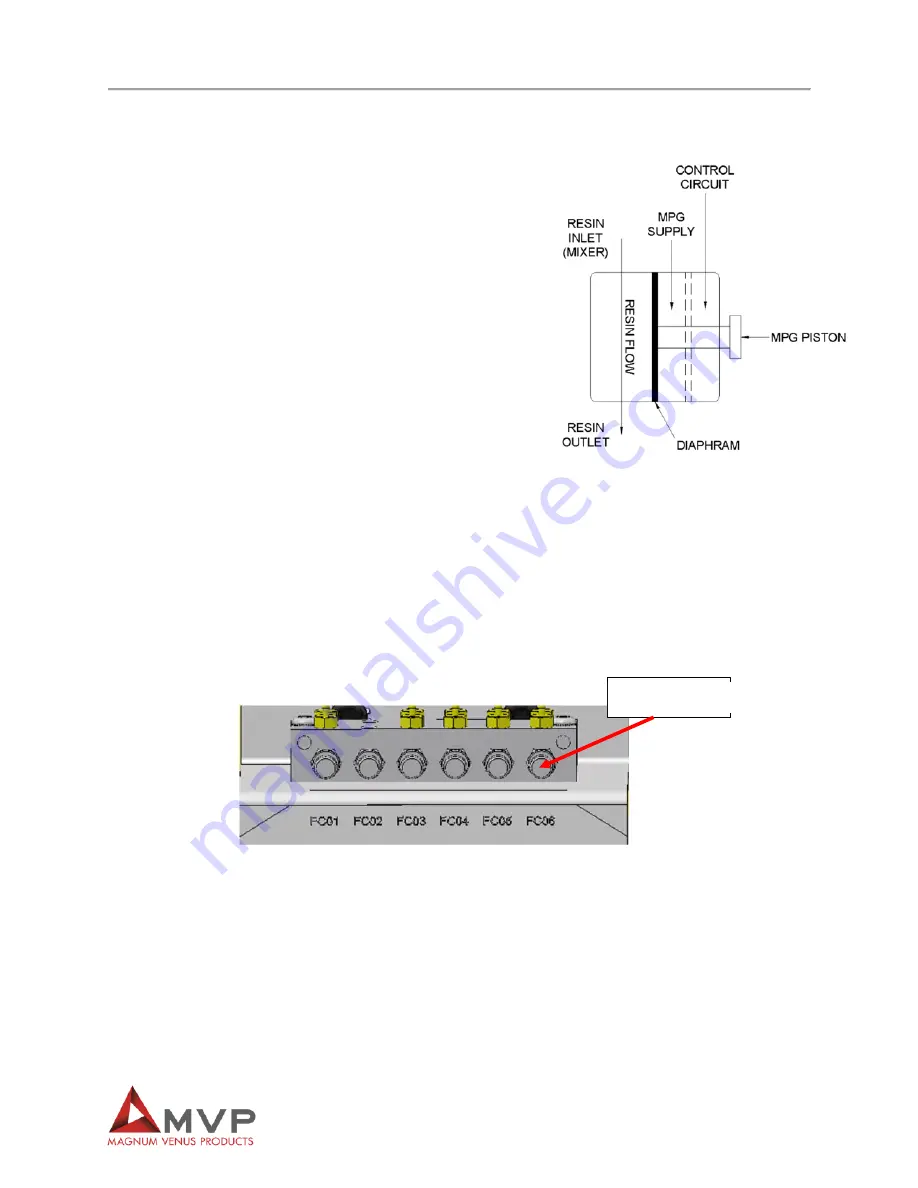
When fluid pressure at the injection head exceeds the
MPG preset level shown on the MPG pressure gauge,
the internal diaphragm moves the MPG piston
outward and leaks air from the line connected to the
control circuit.
As the level/flow of air pressure is reduced by the MPG piloted regulator, the supply pressure to
the pump is reduced, in effect slowing it down. Once the air pressure in the control circuit has
dropped below approximately 15 psi, the pump will shut off. Once the pressure has been restored,
whether by fluid being drawn into the mold, recirculation engage, or blockage cleared from
output line, the system will start up again.
Note
The MPG control is active in recirculation or injection mode. It is normal to
hear air leaking from the MPG block when the MPG is operational.
7. Adjust the MPG settings by turning the knob marked FC06.
Note
The slower the flow of air through the restrictor, the longer the pump will
take to restart. If the restrictor is fully wound in, airflow will be blocked and
the pump will not start. Conversely, if too higher flow of air is supplied to the
circuit, safe and correct operation of the machine cannot be guaranteed.
This flow control is set at factory and should not be adjusted unless
absolutely necessary.
Note
The response of the pump can be further slowed if required by the addition
of an air reservoir on the circuit. Contact MVP for more information.
MPG Adjustment
Summary of Contents for INV2-PAT-7-PRO
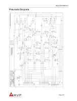
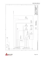
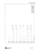
Page 31: ...Operations Manual Page 31 Pneumatic Diagrams ...
Page 32: ...Operations Manual Page 32 ...
Page 33: ...Operations Manual Page 33 ...
Page 35: ...Operations Manual Page 35 ...
Page 36: ...Operations Manual Page 36 ...
Page 37: ...Operations Manual Page 37 ...
Page 38: ...Operations Manual Page 38 ...
Page 39: ...Operations Manual Page 39 ...
Page 40: ...Operations Manual Page 40 ...
Page 41: ...Operations Manual Page 41 ...
Page 42: ...Operations Manual Page 42 ...
Page 43: ...Operations Manual Page 43 ...
Page 44: ...Operations Manual Page 44 ...
Page 45: ...Operations Manual Page 45 ...
Page 46: ...Operations Manual Page 46 ...
Page 47: ...Operations Manual Page 47 ...
Page 48: ...Operations Manual Page 48 ...
Page 49: ...Operations Manual Page 49 ...
Page 50: ...Operations Manual Page 50 ...
Page 51: ...Operations Manual Page 51 ...
Page 52: ...Operations Manual Page 52 ...
Page 53: ...Operations Manual Page 53 ...
Page 54: ...Operations Manual Page 54 ...
Page 55: ...Operations Manual Page 55 ...
Page 56: ...Operations Manual Page 56 ...
Page 57: ...Operations Manual Page 57 ...
Page 58: ...Operations Manual Page 58 ...


