


Operations Manual
Page | 26
11. Repeat step
until you have obtained two or three more samples, then press the
Stop
button.
12. Flush the injection head as necessary.
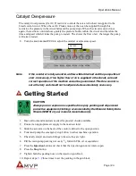
13. Mark the sample containers with the relevant test information, including time, catalyst
percentage, resin temperature, and operator.
14. Press the reset button on the counter to set the count back to zero.
Performing Daily Tasks
Daily Start Up
1. Check all hoses for leaks or damage; replace as needed.
2. Check all material supplies and refill or replace as needed.
Note
Never allow catalyst or resin to run out during an injection.
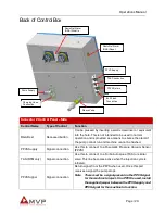
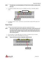
3. Open the main air supply slide valve on the back of the control panel.
4. Press the recirculation button and allow the unit to recirculate for at least 20 strokes or until
no bubbles are visible returning to the catalyst jug from the recirculation tube.
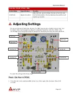
5. Check that the catalyst percentage is set properly.
6. Check the resin pump pressure and adjust as needed.
7. Set the desired number of counts on the stroke counter display.
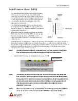
8. Make sure the catalyst pressure gauge reads above 115 to 145 psi (8 to 10 bar) before
beginning the injection.
9. Press the
Stop
button to take the unit out of recirculation mode.
10. Perform a gel test each morning and balance the fluid pressures by following the steps in the
Performing a Gel Test section.
11. Connect the injection hoses from the injection head to the IVx3 valves.
12. Make sure the flush hose from the IVx3 valves are connected to the flush tank.
13. Make sure the IVx3 valve and PPVS are properly connected to the control box and working
correctly (the PPVS should open the IVx3 valve when there is enough vacuum under the
membrane).
The unit is ready for injection.
Daily Shut Down
The preset counter will stop the injection when the set count is reached.
14. If you need to complete the injection before the preset count is reached, press the
Stop
button to close the injection head.
15. Press the reset button on the counter.
Summary of Contents for INV2-PAT-7-PRO
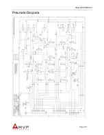
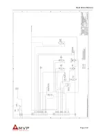
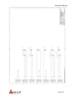
Page 31: ...Operations Manual Page 31 Pneumatic Diagrams ...
Page 32: ...Operations Manual Page 32 ...
Page 33: ...Operations Manual Page 33 ...
Page 35: ...Operations Manual Page 35 ...
Page 36: ...Operations Manual Page 36 ...
Page 37: ...Operations Manual Page 37 ...
Page 38: ...Operations Manual Page 38 ...
Page 39: ...Operations Manual Page 39 ...
Page 40: ...Operations Manual Page 40 ...
Page 41: ...Operations Manual Page 41 ...
Page 42: ...Operations Manual Page 42 ...
Page 43: ...Operations Manual Page 43 ...
Page 44: ...Operations Manual Page 44 ...
Page 45: ...Operations Manual Page 45 ...
Page 46: ...Operations Manual Page 46 ...
Page 47: ...Operations Manual Page 47 ...
Page 48: ...Operations Manual Page 48 ...
Page 49: ...Operations Manual Page 49 ...
Page 50: ...Operations Manual Page 50 ...
Page 51: ...Operations Manual Page 51 ...
Page 52: ...Operations Manual Page 52 ...
Page 53: ...Operations Manual Page 53 ...
Page 54: ...Operations Manual Page 54 ...
Page 55: ...Operations Manual Page 55 ...
Page 56: ...Operations Manual Page 56 ...
Page 57: ...Operations Manual Page 57 ...
Page 58: ...Operations Manual Page 58 ...


