background image

Patriot Multi-Color Gelcoater Operations Manual 

Page | 25  

38. Install the catalyst tip over the spray tip. 

Note 

Use caution not to damage the O-rings on the front of the gun block.  

39. Install the retainer to secure the catalyst tip and spray tip in place.  
40. Spray a test pattern.  
41. Make gelcoat pump pressure adjustments until a fairly uniform pattern is achieved with 

slight horns on either side of the spray fan.  

42. Slowly open the air-assist needle valve located on the side of the gun handle until a soft, 

uniform pattern is achieved.  

Internal Mix 

43. Use a little red grease on the O-rings and threads of the spray tip, catalyst tip, and retainer. 
44. Install the turbulent mixer into the mix chamber.  
45. Insert the static mixer and spray tip onto the air assist housing and screw the air-assist onto 

the gun mix housing.  

Note 

For longer turbulent mixer life, do not overtighten the air assist nozzle housing.  

46. Attach the air-assist tube from the needle valve on the side of the gun handle to the air-assist 

head.  

47. Spray a test pattern.  
48. Make gelcoat pump pressure adjustments until a fairly uniform pattern is achieved with 

slight horns on either side of the spray fan.  

49. Slowly open the air-assist needle valve located on the side of the gun handle until a soft, 

uniform pattern is achieved.  

Performing Daily Tasks 

Daily Start Up – External Mix 

1. Check all hoses for damage; replace as needed.  
2. Check all material supplies and refill or replace as needed.  
3. Open the recirculation valve on the catalyst manifold.  
4. Open the main air inlet valve on the manifold.  
5. Remove the pivot pin from the catalyst drive.  
6. Manually pump the catalyst pump with the catalyst drive until you observe the stream 

returning to the catalyst jug is air free.  

7. Close the recirculation valve on the catalyst manifold.  
8. Manually pump the catalyst pump with the salve arm drive, bringing the catalyst pressure to 

operating pressure of about 100 psi.  

9. Check the pump pressure; if adjustment is needed, press and hold the priming button while 

slowly adjusting the air pressure.  

Summary of Contents for Patriot MVE-PAT-1500-x

Page 1: ...Patriot Multi Color Gelcoater Operations Manual This manual is applicable to the following models MVE PAT 1500 x Rev December 2018 ...

Page 2: ...642 Barbrow Ln Knoxville TN 37932 USA Tel 865 684 4416 TECHNOLOGY CENTER AND MANUFACTURING 1862 Ives Ave Kent WA 98032 USA Tel 253 854 2660 Fax 253 854 1666 E mail info mvpind com For a list of international distributors visit our website at www mvpind com mvp international Use of this product confirms that Magnum Venus Products Inc s standard terms and conditions of sale apply ...

Page 3: ... Operations Manual Page 3 Table of Contents Section Page Table of Contents 3 Safety Warning Information 4 Introduction 15 Getting Started 18 Charging Accumulators 18 Changing Colors 21 Priming the Unit 22 Performing Daily Tasks 25 ...

Page 4: ... HealthAct OSHA Documentation 1910 94 Pertaining to ventilation 1910 106 Pertaining to flammable liquids 1910 107 Pertaining to spray finishing operations particularly paragraph m Organic Peroxides and Dual Component Coatings For Additional information contact the Occupational Safety and Health Administration OSHA at https www osha gov about html Recommended National Fire ProtectionAssociation NFP...

Page 5: ...beled otherwise Cured laminate accumulations of overspray and laminate sandings are highly combustible Do not operate or move electrical equipment when flammable fumes are present Ground all equipment If a spark is seen or felt immediately halt operation Do not operate the equipment until the issue has been identified and repaired Contaminated catalyst may cause fire or explosion Containers may ex...

Page 6: ...k immediate medical attention Inhalation Move the person to fresh air and seek immediate medical attention Do not remove shields covers or safety features on equipment that is in use Never place fingers hands or any body part near or directly in front of the spray gun fluid tip The force of the liquid as it exits the spray tip can shoot liquid through the skin Keep hands and body parts away from a...

Page 7: ...combustion Indicates the risk of contact with moving components that may lead to serious injury or death Indicates that the system or component should be grounded before proceeding with use or repair Indicates the use of lit cigarettes or cigars is prohibited because the materials being used are susceptible to combustion Indicates that the materials and or the process being performed can lead to i...

Page 8: ...e Component Organ System Target Possible Target Known Possible Health Effect Aramid fibers Skin lungs Skin and respiratory irritation contact dermatitis chronic interstitial lung disease Carbon graphite fibers Skin lungs As noted for aramid fibers Glass fibers continuous filament Skin lungs As noted for aramid fibers Hardeners and curing agents Composite Component Organ System Target Possible Targ...

Page 9: ...losion is 10 000 psi per second Some forms of MEKP if allowed to reach their SADT will burst even an open topped container This suggests that it is not possible to design a relief valve to vent this order of magnitude of pressure rate of rise The user should be aware that any closed container be it a pressure vessel surge chamber or pressure accumulator could explode under certain conditions There...

Page 10: ...NG A hazardous situation may be present in your pressurized fluid system Hydro carbon solvents can cause an explosion when used with aluminum or galvanized components in a closed pressurized fluid system pump heaters filters valves spray guns tanks etc An explosion could cause serious injury death and or substantial property damage Cleaning agents coatings paints etc may contain Halogenated Hyrdro...

Page 11: ... and their not being classified as toxic or carcinogenic substances HHC solvents are very desirable in many respects WARNING Do not use Halogenated Hydrocarbon HHC solvents in pressurized fluid systems having aluminum or galvanized wetted parts Magnum Venus Products is aware of NO stabilizers available to prevent HHC solvents from reaction under all conditions with aluminum components in closed fl...

Page 12: ...l accumulations of overspray Fiberglass Reinforced Plastic FRP sandings etc from the building as they occur If this waste is allowed to build up spillage of catalyst is more likely to start a fire in addition the fire would burn hotter and longer Floor coverings if used should be non combustible Spilled or leaked catalyst may cause a fire if it comes in contact with an FRP product over sprayed cho...

Page 13: ... liquid as it exits the spray tip can cause serious injury by shooting liquid through the skin NEVER LOOK DIRECTLY INTO THE GUN SPRAY TIP OR POINT THE GUN AT OR NEAR ANOTHER PERSON DANGER Contaminated catalyst may cause fire or explosion Before working on the catalyst pump or catalyst accumulator wash hands and tools thoroughly Be sure work area is free from dirt grease or resin Clean catalyst sys...

Page 14: ...requently depends upon the nature of the chemical Emergency Stop Procedure In an emergency follow these steps to stop a UPS System 1 The ball valve located where the air enters the power head of the resin pump should be moved to the OFF or closed position Note The open or on position is when the ball valve handle is parallel in line with the ball valve body The closed or off position is when the b...

Page 15: ...P Patriot Multi Color Gelcoater The following procedures are included Step by step assembly and disassembly Installation start up and shut down instructions Step by step operation instructions Please read this manual carefully and retain for future reference Follow the steps in the order given otherwise you may damage the equipment or injure yourself Component Assemblies MVP s Patriot Multi Color ...

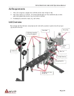
Page 16: ...e caution when using quick disconnects they may restrict air flow 3 Preferably the air will be clean dry and oil free Unit Overview Below helps identify the main components and controls the operator needs to know for proper operation for the unit Powerhead Catalyst Jug Carriage Assembly Slave Arm Catalyst Pump Fluid Sections 4 Color Unit Shown Filter Surge Chambers 4 Color Unit Shown Air Manifold ...

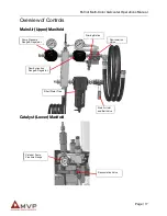
Page 17: ...erview of Controls Main Air Upper Manifold Catalyst Lower Manifold Main Air Inlet and Ball Valve Filter Water Trap Priming Button Recirculation Valve Ram Extraction Gauge Regulator Pump Pressure Gauge Regulator Catalyst Pump Pressure Gauge Recirculation Valve ...

Page 18: ...r hose from the manifold to the flush tank and connect the yellow flush tube from the gun to the tank 10 Check to make sure all hose fittings and connections are tight 11 Connect an adequate air supply 12 Open the incoming air supply ball valve all the way Note The main air supply ball valve is a safety ball valve and must be fully open or closed or air will leak When the valve is close the air pr...

Page 19: ... charge by inserting a blunt object such as an Allen wrench into the top of the charging valve 4 Push the quick coupling on the charging hose onto the charging valve on top of the resin accumulator and hold in place for approximately 5 seconds Note If air is exiting the front of the gun or valve during accumulator charging the poly ball in the accumulator is not seating properly Repair the accumul...

Page 20: ...ilding Note If air is exiting the front of the gun or valve during accumulator charging the poly ball in the accumulator is not seating properly Repair the accumulator as needed 16 Disconnect the air hose form the charging pump and remove the charging pump hose from the resin accumulator 17 Check the top of the accumulator for leaks by applying a light fluid such as water to the top of the accumul...

Page 21: ...he charging hose form the resin accumulator 30 Check the top of the accumulator for leaks by applying a light fluid such as water to the top of the accumulator valve body 31 If any air leaks are detected remove and repair the charging valve 32 Close the gun and flush into an appropriate container or close the appropriate valve 33 Repeat this procedure on the catalyst accumulator Changing Colors 1 ...

Page 22: ... the desired fluid section and align the shafts Note The air motor or fluid section shaft may need to be moved up or down to allow proper alignment 14 When the shafts are properly aligned and touching end to end push the sleeve up and re install the two coupling half shell connectors 15 Tighten the two clamp bolts by turning clockwise 16 Charge the gelcoat accumulator if applicable to your system ...

Page 23: ...catalyst manifold 12 Remove the pivot pin on the catalyst drive linkage 13 Using the catalyst drive hand prime catalyst back to the jug through the recirculation valve until there is no air in the tube 14 Close the recirculation valve 15 Lock or hold the gun trigger in the open position over an appropriate container 16 Remove the pivot pin from the catalyst drive linkage 17 Use the catalyst drive ...

Page 24: ...onnect for 5 to 10 seconds and disengage 32 Close the ball valve below the inline filter Pressurize Fluids 33 Push the priming button and slowly increase the gelcoat pump regulator to between 40 and 50 psi as a starting point Note On the air manifold the blue valve is the safety override The small brass button is the priming button The safety override valve automatically opens and closes the air s...

Page 25: ...assist tube from the needle valve on the side of the gun handle to the air assist head 47 Spray a test pattern 48 Make gelcoat pump pressure adjustments until a fairly uniform pattern is achieved with slight horns on either side of the spray fan 49 Slowly open the air assist needle valve located on the side of the gun handle until a soft uniform pattern is achieved Performing Daily Tasks Daily Sta...

Page 26: ... arm drive bringing the catalyst pressure to operating pressure between 100 and 200 psi 23 Check the pump pressure if adjustment is needed press and hold the priming button while adjusting the air pressure 24 Replace the pivot pin into the catalyst pump drive 25 Insert the distribution ring into the mix chamber locating rim 26 Place the mix housing seal into the mix chamber locating rim 27 Insert ...

Page 27: ...pe the face of the air assist nozzle after flushing 38 Turn off the main air ball valve at the air manifold 39 Release the solvent flush tank pressure 40 Disassemble the air assist and clean with solvent 41 Remove the mix housing and clean 42 Wipe the gun block face with a clean rag 43 Hang the gun with the gun block exit holes facing downward ...

Reviews: