
47
EN
M1.1.HB250CF.NLFREN - 05012018
U
U
S
S
E
E
R
R
’
’
S
S
M
M
A
A
N
N
U
U
A
A
L
L
- 13 -
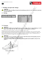
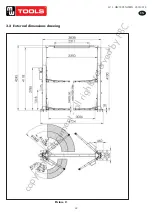
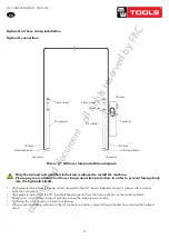
7.3 Installation
Column installation
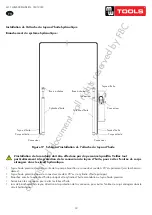
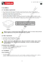
a. Set up the column
set up the installed main and sub columns on the concrete foundation, with distance at 2680mm which is suitable to
install the oil hose cover plate, make sure the two columns are in same level.(refer below picture).
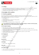
b. Install the expansion bolt
The expansion bolt must work after finished the maintenance of the concrete foundation, otherwise, it will affect
the locking quality.
-Adjust the position & vertical degree of the two columns.
-Use a hammer clip with
φ
18mm impact bit(the length of the bit
≥180mm )
drill the hole from the base plate hole till
depth 160MM, and clean the hole with dust cleaner
- Use the light hammer to knock the expansion bolts to the 10 holes (no need to insert the center expansion nail, fix
it after finished the level adjustment)
Picture 9 picture 10 picture 11
Picture 12 picture 13
c. Level adjustment
- Use a transparent horizontal tube or gradienter to exam the all around level of the master & vice column, if level
degree is no problem, insert the center expansion nail, heavy hammer knocks the center expansion nail, tighten the
nuts after finished to install the top beam and the master & vice column is still in level degree.
If the concrete foundation is under the maintenance, please do not knock in the center expansion bolt. The
space between the base plate and ground must fill with cement mortar after adjust the level degree
.
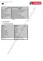
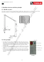
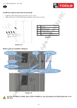
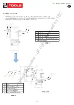
d. Top beam installation
- After raised the two columns stand up, put the top beam on the top of the two columns with crane and use bolts to
fix it.
ATTENTION:pay attention to the top beam while installating it for it might drop from middle-air and do harm to
person.
A
top beam
B
M8×35 full thread hex flanges bolt
C
φ8 flat washer
D
φ8 spring washer
E
φ8
nuts
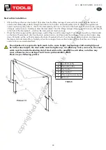
3. Level adjustment:
- Use a transparent horizontal tube or level indicator to exam the all around level of the master and vice column, if level
degree is no problem, insert the center expansion nail, heavy hammer knocks the center expansion nail, tighten the nuts
after finished to install the top beam and the master and vice column is still in level degree.
If the concrete foundation is under the maintenance, please do not knock in the center expansion
bolt. The space between the base plate and ground must fill with cement mortar after adjust the
level degree�
4. Top beam installation:
- After raised the two columns stand up, put the top beam on the top of the two columns with crane and use bolts to fix it.
ATTENTION!
Pay attention to the top beam while installing it for it might drop from middle-air and do harm to
person�
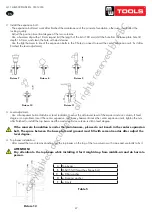
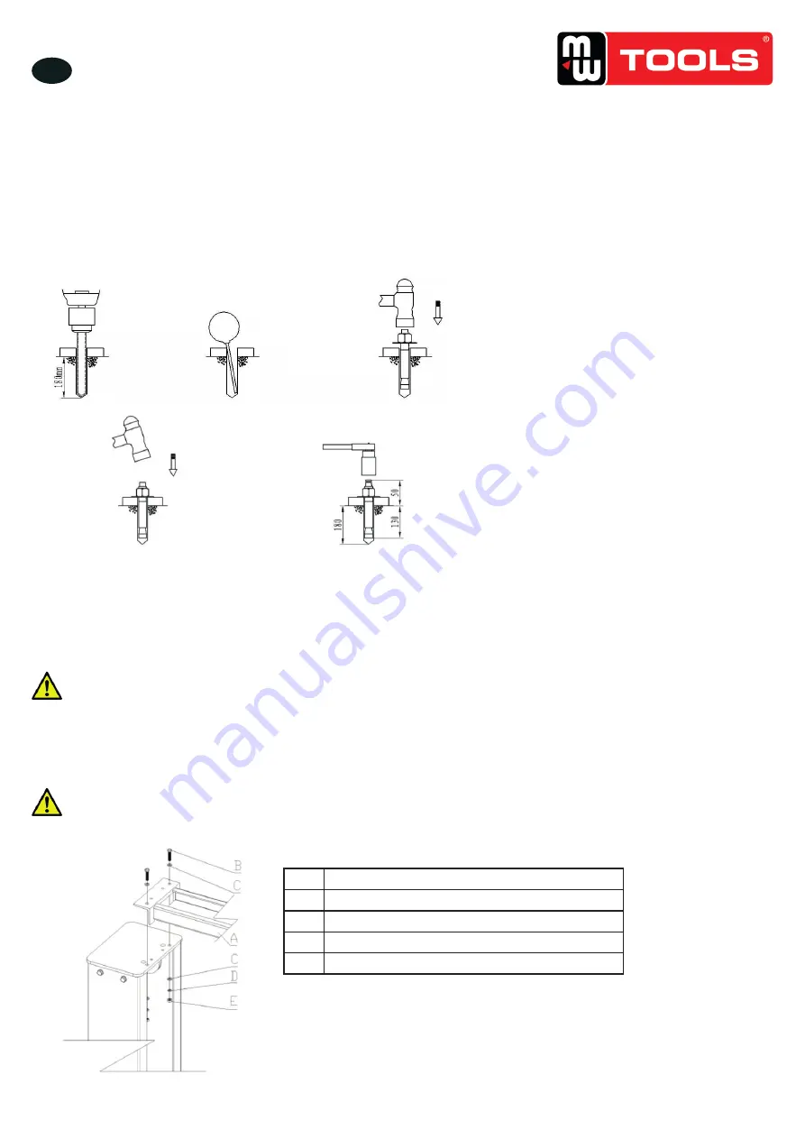
2. Install the expansion bolt:
- The expansion bolt must work after finished the maintenance of the concrete foundation, otherwise, it will affect the
locking quality.
- Adjust the position & vertical degree of the two columns.
- Use a hammer clip with φ18 mm impact bit (the length of the bit ≥180 mm) drill the hole from the base plate hole till
depth 160 mm, and clean the hole with dust cleaner
- Use the light hammer to knock the expansion bolts to the 9 holes (no need to insert the center expansion nail, fix it after
finished the level adjustment)
U
U
S
S
E
E
R
R
’
’
S
S
M
M
A
A
N
N
U
U
A
A
L
L
- 13 -
7.3 Installation
Column installation
a. Set up the column
set up the installed main and sub columns on the concrete foundation, with distance at 2680mm which is suitable to
install the oil hose cover plate, make sure the two columns are in same level.(refer below picture).
b. Install the expansion bolt
The expansion bolt must work after finished the maintenance of the concrete foundation, otherwise, it will affect
the locking quality.
-Adjust the position & vertical degree of the two columns.
-Use a hammer clip with
φ
18mm impact bit(the length of the bit
≥180mm )
drill the hole from the base plate hole till
depth 160MM, and clean the hole with dust cleaner
- Use the light hammer to knock the expansion bolts to the 10 holes (no need to insert the center expansion nail, fix
it after finished the level adjustment)
Picture 9 picture 10 picture 11
Picture 12 picture 13
c. Level adjustment
- Use a transparent horizontal tube or gradienter to exam the all around level of the master & vice column, if level
degree is no problem, insert the center expansion nail, heavy hammer knocks the center expansion nail, tighten the
nuts after finished to install the top beam and the master & vice column is still in level degree.
If the concrete foundation is under the maintenance, please do not knock in the center expansion bolt. The
space between the base plate and ground must fill with cement mortar after adjust the level degree
.
d. Top beam installation
- After raised the two columns stand up, put the top beam on the top of the two columns with crane and use bolts to
fix it.
ATTENTION:pay attention to the top beam while installating it for it might drop from middle-air and do harm to
person.
A
top beam
B
M8×35 full thread hex flanges bolt
C
φ8 flat washer
D
φ8 spring washer
E
φ8
nuts
Picture 7
Picture 8
Picture 9
Picture 10
Picture 11
A
Top beam
B
M8x35 full thread hex flange bolt
C
φ 8 flat washer
D
φ 8 spring washer
E
φ 8 nuts
Table 5
Picture 12
copyrighted
document
- all
rights
reserved
by
FBC


