


13
FR
M1.3.BT200-BT200M.NLFREN 13112018
.1211 . V201301
- 2 -
3. Technical data
External locking rim dimensions
10~21
"
Internal locking rim dimensions
12~24
"
Max. Wheel diameter
1040mm(41
"
)
Max. Wheel width
355mm(14
"
)
Working Pressure
8-10bar
Power supply
110V (1ph)/ 220V (1ph)/ 380V (3ph)
Optional Motor power
0.75/0.55/1.1 kw
Max. Rotating Torque (Turntable)
1078 Nm
Overall Dimension
96*76*93cm
Noise Level
75 Db
Remark
:
Rim dimensions defined at above table are based on the iron wheel rims. Aluminum rims are thicker than the
iron wheel rims, so here above rim dimensions are just for the reference.
Here above machine versions can be equipped with Rapid Tire Inflation Device (client optional device),
IT-suffix version, accessory details can be found at the IT-suffix version exploded drawing.
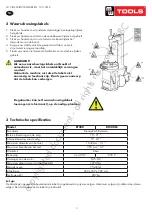
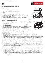
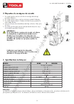
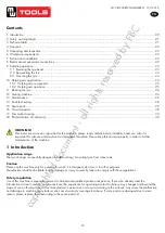
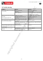
4. Transport:
When transporting, the machine should be with original package and placed according to the mark on the package.
For the already packaged machine should be handled with a corresponding tonnage forklift for loading and unloading.
The location to insert the fork feet shown as
Fig 1
5. Unpacking & Inspection:
Pull out the nail which is nailed on the plate with tip jaw; unpack the carton and plastic cover. Check and make sure
all parts shown on the spare parts list are included. If any parts are missing or broken, please do not use the machine
and contact the manufacturer or dealer ASAP.
Fig 1 Fig 2 Fig 3
6. Workplace requirements:
Choose workplace in compliance with safety regulations. Connect power supply and air source according to manual
and workplace must have good air condition; in order to make the machine run well, its workplace requires at least
clear space from each wall shown as
Fig 2
. If installing it outdoor, it must be protected by roof against rain and
sunshine.
Warning: the machine with motor must not be operated in explosive atmosphere
.
Fig. 1
.1211 . V201301
- 2 -
3. Technical data
External locking rim dimensions
10~21
"
Internal locking rim dimensions
12~24
"
Max. Wheel diameter
1040mm(41
"
)
Max. Wheel width
355mm(14
"
)
Working Pressure
8-10bar
Power supply
110V (1ph)/ 220V (1ph)/ 380V (3ph)
Optional Motor power
0.75/0.55/1.1 kw
Max. Rotating Torque (Turntable)
1078 Nm
Overall Dimension
96*76*93cm
Noise Level
75 Db
Remark
:
Rim dimensions defined at above table are based on the iron wheel rims. Aluminum rims are thicker than the
iron wheel rims, so here above rim dimensions are just for the reference.
Here above machine versions can be equipped with Rapid Tire Inflation Device (client optional device),
IT-suffix version, accessory details can be found at the IT-suffix version exploded drawing.
4. Transport:
When transporting, the machine should be with original package and placed according to the mark on the package.
For the already packaged machine should be handled with a corresponding tonnage forklift for loading and unloading.
The location to insert the fork feet shown as
Fig 1
5. Unpacking & Inspection:
Pull out the nail which is nailed on the plate with tip jaw; unpack the carton and plastic cover. Check and make sure
all parts shown on the spare parts list are included. If any parts are missing or broken, please do not use the machine
and contact the manufacturer or dealer ASAP.
Fig 1 Fig 2 Fig 3
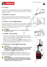
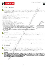
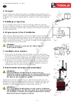
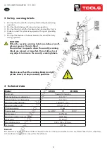
6. Workplace requirements:
Choose workplace in compliance with safety regulations. Connect power supply and air source according to manual
and workplace must have good air condition; in order to make the machine run well, its workplace requires at least
clear space from each wall shown as
Fig 2
. If installing it outdoor, it must be protected by roof against rain and
sunshine.
Warning: the machine with motor must not be operated in explosive atmosphere
.
Fig. 2
.1211 . V201301
- 2 -
3. Technical data
External locking rim dimensions
10~21
"
Internal locking rim dimensions
12~24
"
Max. Wheel diameter
1040mm(41
"
)
Max. Wheel width
355mm(14
"
)
Working Pressure
8-10bar
Power supply
110V (1ph)/ 220V (1ph)/ 380V (3ph)
Optional Motor power
0.75/0.55/1.1 kw
Max. Rotating Torque (Turntable)
1078 Nm
Overall Dimension
96*76*93cm
Noise Level
75 Db
Remark
:
Rim dimensions defined at above table are based on the iron wheel rims. Aluminum rims are thicker than the
iron wheel rims, so here above rim dimensions are just for the reference.
Here above machine versions can be equipped with Rapid Tire Inflation Device (client optional device),
IT-suffix version, accessory details can be found at the IT-suffix version exploded drawing.
4. Transport:
When transporting, the machine should be with original package and placed according to the mark on the package.
For the already packaged machine should be handled with a corresponding tonnage forklift for loading and unloading.
The location to insert the fork feet shown as
Fig 1
5. Unpacking & Inspection:
Pull out the nail which is nailed on the plate with tip jaw; unpack the carton and plastic cover. Check and make sure
all parts shown on the spare parts list are included. If any parts are missing or broken, please do not use the machine
and contact the manufacturer or dealer ASAP.
Fig 1 Fig 2 Fig 3
6. Workplace requirements:
Choose workplace in compliance with safety regulations. Connect power supply and air source according to manual
and workplace must have good air condition; in order to make the machine run well, its workplace requires at least
clear space from each wall shown as
Fig 2
. If installing it outdoor, it must be protected by roof against rain and
sunshine.
Warning: the machine with motor must not be operated in explosive atmosphere
.
Fig. 3
.1211 . V201301
- 3
–
7. Position and installation:
1. Unscrew the nuts at the bottom, position the machine and calibrate it with the
horizontal rule. Mount the machine with all the screws and to ensure the machine is
stable. Make sure the system is equipped with a good grounding circuit for prevent
electric leakage. And have operation range of ground for skid prevention.
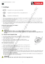
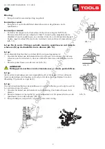
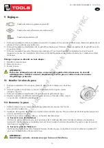
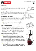
2. Unscrew the nut A on the cabinet body B as shown in
Fig 3
.
Lift the column C; mount it on the machine body B by using the nut A through the
bolt located on the machine body B. If the column becom
e
s loose after a period of
using, tight them immediately. Otherwise the result of damage to the tyre may
happen.
8. Electricity and Pneumatic connections:
Caution: Before installation and connection, check to be sure that the electricity
power supply corresponds to the machine technical data. All the installation of
electric and pneumatic devices must be operated by a professional electrician
.
Connect the compressed air connector which is on the machine right side with
compressed air system. The electric grid that the machine connects to must have
fuses protection device and good outer cover grounding protection. Install the
leakage automatic air switch on the maim power supply, leakage current is set at 30A
Caution: No power plug for this machine, the user should self-connect one power plug no less than 16A as well
as in line with the machine voltage. Or directly connect with the power supply according to the above
requirements
.
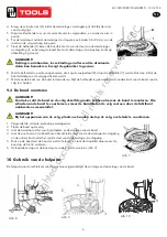
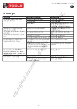
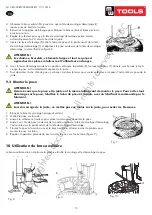
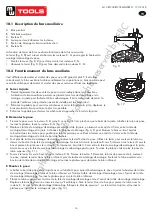
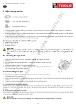
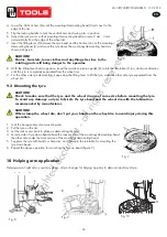
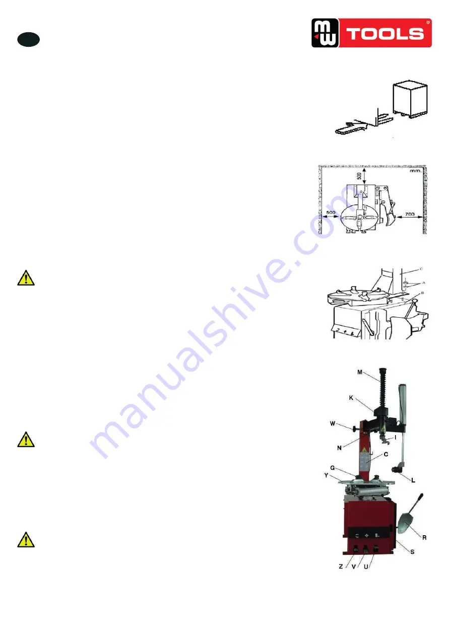
9. Adjusting operation:
Turntable Rotation Pedal (Z)
Bead Breaker Pedal (U)
Jaws open and close Pedal (V)
1)
Tread the Turntable Rotation Pedal (Z), Turntable (Y) clockwise rotation; Lift up the Turntable Rotation
Pedal (Z), Turntable (Y) counterclockwise rotation.
2)
Tread Bead Breaker Pedal (U), Bead Breaker shovel (R) close toward inside; release Bead Breaker Pedal (U),
Bead Breaker shovel (R) return to original position.
3)
Tread Jaws open and close Pedal (V), four clamps (G) on the turntable open; tread again, four clamps (G)
close. When the pedal is in the middle position, the four clamps stop moving.
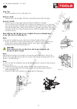
Tyre changer operation is consisted of three parts:
1
)
Breaking the tyre bead
2
)
Demounting the tyre
3
)
Mounting the tyre
Caution: Before any operations, don
’
t wear loose clothing and wear protective hat, gloves, and skid-proof shoes.
Ensure to exhaust the air in the tyre completely, and remove all the wheel weights from the rim.
Fig 4
Fig. 4
4 Transport
Lors du transport, la machine doit être dans son emballage original et placée selon les
marques sur celui-ci. La machine emballée doit être transportée, déplacée et déposée par
un élévateur à fourche d’une capacité suffisante. La figure 1 montre comment placer la
fourche.
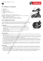
5 Déballage et inspection
Avec une tenaille, enlevez le clou se trouvant sur la plaque. Enlevez le carton et le
couvercle en plastique. Comparez le contenu de l’emballage avec la liste de colisage. Si
une pièce est manquante ou endommagée, n’utilisez pas la machine et contactez votre
revendeur immédiatement.
6 Exigences pour le lieu d’installation
Veillez à ce que l’espace de travail soit conforme à la réglementation en matière de
sécurité. Branchez l’alimentation électrique et la source d’air comprimé comme indiqué, et
veillez à ce que l’atelier soit bien aéré. Veillez à prévoir un espace suffisant autour de la
machine, comme illustré en figure 2. Si la machine est installée à l’extérieur, un toit doit la
protéger de la pluie et des rayons du soleil.
ATTENTION !
La machine motorisée ne peut pas être utilisée dans un
environnement explosif.
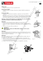
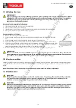
7 Installation de la machine
1.
Dévissez les écrous dans le bas, placez la machine en vérifiant qu’elle est bien
horizontale. Montez la machine avec toutes les vis et assurez-vous qu’elle est stable.
Assurez-vous que l’installation électrique est munie d’une bonne prise de terre pour
prévenir les fuites électriques. Veillez également à ce que le sol soit antidérapant.
2.
Dévissez l’écrou A sur le châssis B comme illustré en figure 3. Levez la colonne
C. Montez-la sur le châssis B en utilisant l’écrou A et le boulon se trouvant sur le
châssis B. Si la colonne se desserre après une période d’utilisation, resserrez-la
immédiatement. Sinon, le pneu pourrait être endommagé.
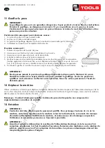
8 Branchements électriques et pneumatiques
ATTENTION !
Avant l’installation et le branchement, assurez-vous que
l’installation électrique corresponde aux données techniques de la
machine. Les branchements électriques et pneumatiques doivent
être effectués par un électricien qualifié.
Branchez le raccord d’air comprimé situé sur le côté droit de la machine avec votre
système d’air comprimé. Le boîtier électrique sur lequel vous branchez la machine doit
être équipé d’un disjoncteur et d’une bonne mise à la terre. Installez l’interrupteur de
protection sur l’alimentation principale. Le courant de fuite est de 30 A.
ATTENTION !
Il n’y a pas de fiche d’alimentation sur cette machine. L’utilisateur
doit installer lui-même une fiche d’au moins 16 A, et qui correspond
à la tension de la machine. Il peut également brancher la machine
directement selon les exigences ci-dessus.
copyrighted
document
- all
rights
reserved
by
FBC


