
17
FR
M1.3.BT200-BT200M.NLFREN 13112018
.1211 . V201301
- 6 -
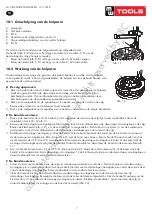
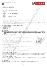
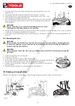
b. Demount tyre
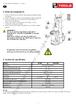
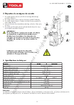
1. Press tyre with right pressing roller C,G to a position 3cm lower than rim edge, lubricate tyre bead, rotate
turntable, lift roller C,G. ( Fig 9 )
2. Move demounting/mounting head close to edge of rim, keep a 2-3mm gap between demounting/mounting head
and rim plane
,
operate locking handle
(
K
,
Fig 4
)
to lock vertical arm
,
adjust screw bolt in column to position swing
arm, make sure 2-3mm gap between demounting/mounting head and rim edge side
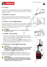
3. Nearby demounting/mounting head, insert lift lever
N
into tyre
,
use lift lever to lift bead upon knob of
demounting / mounting head. Manually rotate roller C to inner side
,
pull handle D down, make roller C to press rim
,
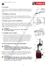
keep 3-5mm gap between demounting/mounting head and rim, make sure demounting/mounting head not damage
rim, rotate turntable, demount tyre upper bead ( Fig 11)
4. Push handle D up
,
lift roller C,G
,
press switch F
,
loosen right pressing arm,
Lift tyre up, insert lifting level into bottom tyre bead nearby demounting/mounting head, lift bead upon knob of
demounting / mounting head and rotate turntable to demount down tyre bead
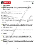
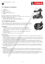
c. Mount tyre
1. Lubricate tyre and rim edge with lubricant to avoid damage of tyre. Adjust height of demounting/mounting head
and make tyre bottom bead upon rear of demounting/mounting head and below front of demounting/mounting head.
Rotate turntable to mount bottom bead.
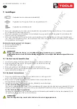
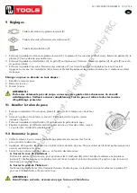
2. Make tyre top bead upon rear of demounting/mounting head and below front of emounting/mounting head, move
right pressing arm and make sure it is locked, pull handle D down to make roller C,G to press top bead to position
below demounting/mounting head. Lock pressing block 1 on rim edge, rotate turntable, finish tyre mounting. (Fig
12)
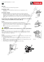
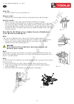
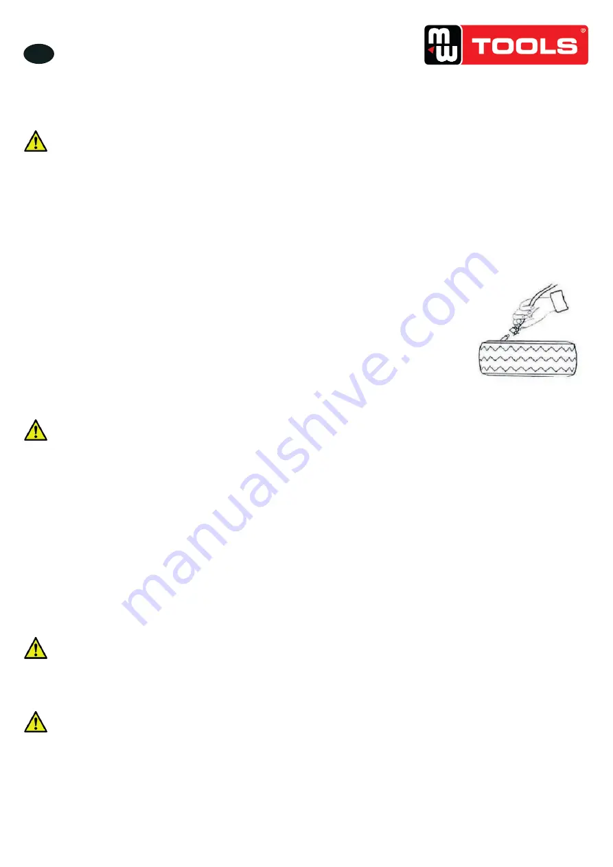
11. Inflating the tire:
Importance: It is very dangerous during inflating operation, take carefully and
comply with instruction. When inflating, it will turn to be extremely dangerous if
problems happen to tyre or rim. The possible burst force tire goes upward and
outward, the big power may cause injury or death of the operator or the people
around
.
Tyre may burst caused by following:
1) The wheel rim and the tyre are not of the same size;
2) The tyre or the wheel rim is damaged;
3) The pressure of tyre inflation is over the max. pressure recommended by manufacturer;
4) The operator fail to comply with the safety regulation;
Please operate as follows:
1) Remove the valve cap from the valve stem;
2) Check to make sure the air nozzle is pressed down completely over the threads of the valve stem.
3) Check to make sure that the tyre and the wheel rim are of the same size;
4) Lubricate both the tyre bead and the wheel rim, additional lubrication is required if needed;
5) Inflate the tyre with break, while inflating, check the pressure listed on the pressure gauge, also check whether
the bead is fixed or not. Repeat operation above until the bead is secured; you need take special steps when inflating
convex rim or double convex rim;
6) Continue inflating and check the air pressure frequently until to reach the required pressure.
Note:
Never exceed the max. inflation pressure given by the tyre manufacturer.
Keep hands and your body away from inflating tyres.
Only specially trained persons are allowed to perform the operations, do not allow other to operate or be near
the tyre changer
.
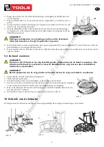
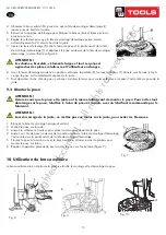
Fig 13
Fig. 13
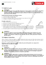
11 Gonfler le pneu
IMPORTANT !
Le gonflage du pneu est une opération dangereuse. Soyez prudent et suivez bien les instructions.
Pendant le gonflage, un danger peut survenir s’il y a un problème avec le pneu ou la jante.
L’éclatement du pneu peut provoquer de graves blessure et même la mort de l’utilisateur et des
personnes présentes alentour.
L’éclatement du pneu peut avoir plusieurs causes :
1.
La jante et le pneu n’ont pas la même taille,
2.
Le pneu ou la jante sont endommagés,
3.
La pression de gonflage dépasse la pression maximale recommandée par le fabricant,
4.
L’utilisateur ne respecte pas les règlements de sécurité.
Procédez comme suit :
1. Enlevez le capuchon de la valve du pneu.
2.
Assurez-vous que l’embout est placé complètement sur la valve.
3. Assurez-vous que le pneu et la jante ont la même taille.
4.
Lubrifiez le talon du pneu et la jante si nécessaire.
5.
Gonflez le pneu en vous arrêtant ponctuellement pour vérifier la pression sur le manomètre.
Vérifiez également si le talon est fixé ou non. Répétez cette étape jusqu’à ce que le talon soit
fixé. Si la jante est convexe ou double convexe, vous devez prendre des mesures spéciales.
6.
Continuez à gonfler et à vérifier la pression jusqu’à ce que la pression requise soit atteinte.
ATTENTION !
Ne dépassez jamais la pression de gonflage maximale indiquée par le fabricant de pneus.
Gardez les mains et le corps à distance du pneu pendant le gonflage. Seules les personnes
qualifiées sont autorisées à effectuer cette opération. Tenez les autres personnes à l’écart du
démonte-pneus.
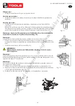
12 Déplacer la machine
Utilisez un élévateur à fourche pour déplacer la machine. Débranchez le démonte-pneus de l’alimentation électrique et de la
source d’air comprimé, soulevez la base de la machine et insérez la fourche de l’engin de levage. Levez ensuite la machine,
allez la placer à l’endroit souhaité et fixez-la.
Remarque : L’endroit choisi pour installer le démonte-pneu doit répondre aux exigence des
réglementations en matière de sécurité.
13 Entretien
ATTENTION !
L’entretien doit être effectué par du personnel qualifié. Pour prolonger la durée de vie de la
machine, entretenez régulièrement la machine selon les instructions de ce manuel. Un manque
d’entretien affecterait la fiabilité de la machine, et même causer des dommages corporels à
l’utilisateur et aux autres personnes se trouvant à proximité.
ATTENTION !
Avant tout entretien, débranchez la machine de l’alimentation électrique et de la source d’air
comprimé, et enfoncez 3~4 fois la pédale d’ouverture/fermeture des mâchoires ou de rotation du
plateau, pour évacuer tout l’air comprimé de la machine. Les pièces endommagées doivent être
remplacées par des pièces d’origine.
copyrighted
document
- all
rights
reserved
by
FBC


