
18
FR
M1.3.BT200-BT200M.NLFREN 13112018
Chaque jour :
•
Nettoyez la machine une fois par jour après le travail.
Une fois par semaine :
•
Nettoyez les saletés sur le plateau tournant avec du diesel et lubrifiez les glissières des
mâchoires.
Une fois par mois :
•
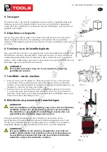
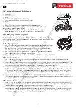
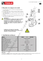
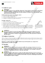
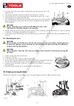
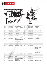
Vérifiez le niveau d’huile dans le nébulisateur, remplissez avec de l’huile SAE30 si
nécessaire.
Dévissez la vis (E) avec une clé hex. Enfoncez 5-6 fois la pédale d’ouverture/fermeture
des mâchoires ou du plateau tournant, et vérifiez si l’huile du nébulisateur tombe goutte à
goutte. Sinon, ajustez la vis (D) qui contrôle l’huile avec un petit tournevis (fig. 14).
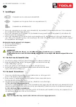
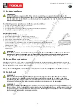
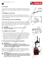
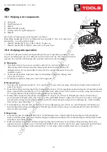
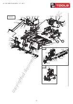
Remarque : Après les 20 premiers jours d’utilisation, fixez les mâchoires en
resserrant les vis (B) sur le plateau tournant (fig. 15).
Remarque :
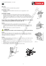
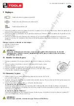
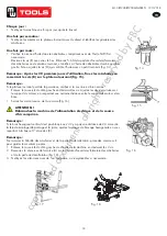
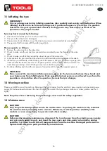
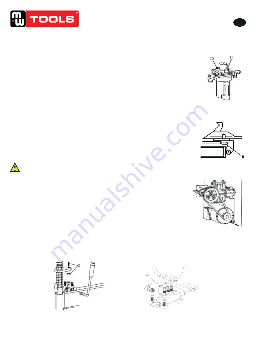
Si le plateau tournant perd de la puissance, vérifiez si la courroie est bien serrée :
• Enlevez le couvercle du côté gauche en dévissant les vis. Ajustez les deux vis situées sur
le support du moteur, en respectant une certaine distance entre le support du moteur et sa
base.
•
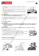
Serrez les vis de tension de la courroie (fig. 16).
ATTENTION !
Débranchez la machine de l’alimentation électrique et de la source
d’air comprimé.
Remarque :
Si le bras hexagonal vertical n’est pas bloqué ou s’il n’y a pas une distance de 2-3 mm entre
la tête de montage/démontage et la jante, ajustez la plaque de blocage hexagonale en vous
reportant à la figure 17 et ajustez (X).
Remarque :
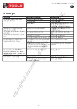
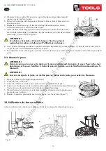
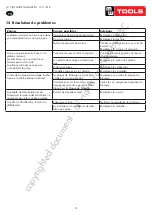
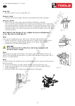
Pour assurer la fiabilité des mâchoires et de la pelle du décolle-talon, procédez comme suit
pour garder leurs valves propres :
1. Enlevez le couvercle du côté gauche du châssis de la machine en dévissant les 2 vis.
2. Desserrez le silencieux de la valve (A) sur la pédale d’ouverture/fermeture des mâchoires
et de la pelle du décolle-talon (fig. 18).
3.
Nettoyez les silencieux avec de l’air comprimé, ou remplacez-les si nécessaire.
.1211 . V201301
- 7
–
12. Moving machine:
Please use forklift to move the machine. Disconnect the tyre changer from the electricity power supply and
pneumatic power supply, lift the base board and insert the feet of forklift. Then mount the tyre changer machine to a
new position and fix it tightly.
Note: the place chosen for fixing the tyre changer must meet the safety regulation
.
13. Maintenance:
Caution: only the professional persons can do the maintenance. To prolong the machine's life, maintain the
machine timely according to the manual. Otherwise, it will impact the reliability of the machine or even cause
injury to operator and others nearby
.
Caution: before performing any maintenance, disconnect the tyre changer from the
electric power supply and pneumatic power supply, and tread the Jaws open and close
Pedal or Turntable Rotation Pedal for 3~4 times to evacuate all compressed air from the
machine. Damaged parts must be replaced by professional persons with the spare parts
provided by manufacturer.
- Clean the machine once every day after work. Clean the dirt on the turntable with diesel oil
once per week and lubricate the slides and clamps.
- Following maintenance must be done at least once per month:
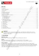
Check oil level in Oil Fog Maker, please be filled with SAE30# oil if need.
Unscrew with hex wrench (E). Based on connection of compressed air, first to
tread Jaws open and close Pedal or Turntable Rotation Pedal 5-6 times, and
then check whether oil in Oil Fog Maker drops down a drip of oil. For
continuous operation, tread twice every time, drop down a drip of oil,
otherwise adjust the screw (D) that controlled oil enter with minus screwdriver.
(Fig 14)
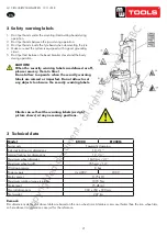
Note: After the first 20 days of use, retighten the jaws with tightening screws (B) on the Turntable (Fig 15)
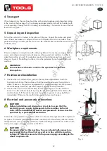
Note: in the event of turntable lose power, check to see if the belt is tight as follow steps:
Remove the left side cover by unscrewing the screws; adjust two screws located on the motor support, keep a
suitable distance between motor support and motor base; tight the screws for the belt tension
.(
Fig 16
)
Caution: please disconnect the machine from electric power supply and pneumatic power supply.
Note: If Hexagonal Vertical Arm not be locked or not meet the requirement that 2-3mm from the bottom of
Mounting/demounting head to rim, please adjust Hexagonal Locking Plate, refer to Fig 17 and adjust the (X)
.
Fig 14
Fig 15
Fig. 14
.1211 . V201301
- 7
–
12. Moving machine:
Please use forklift to move the machine. Disconnect the tyre changer from the electricity power supply and
pneumatic power supply, lift the base board and insert the feet of forklift. Then mount the tyre changer machine to a
new position and fix it tightly.
Note: the place chosen for fixing the tyre changer must meet the safety regulation
.
13. Maintenance:
Caution: only the professional persons can do the maintenance. To prolong the machine's life, maintain the
machine timely according to the manual. Otherwise, it will impact the reliability of the machine or even cause
injury to operator and others nearby
.
Caution: before performing any maintenance, disconnect the tyre changer from the
electric power supply and pneumatic power supply, and tread the Jaws open and close
Pedal or Turntable Rotation Pedal for 3~4 times to evacuate all compressed air from the
machine. Damaged parts must be replaced by professional persons with the spare parts
provided by manufacturer.
- Clean the machine once every day after work. Clean the dirt on the turntable with diesel oil
once per week and lubricate the slides and clamps.
- Following maintenance must be done at least once per month:
Check oil level in Oil Fog Maker, please be filled with SAE30# oil if need.
Unscrew with hex wrench (E). Based on connection of compressed air, first to
tread Jaws open and close Pedal or Turntable Rotation Pedal 5-6 times, and
then check whether oil in Oil Fog Maker drops down a drip of oil. For
continuous operation, tread twice every time, drop down a drip of oil,
otherwise adjust the screw (D) that controlled oil enter with minus screwdriver.
(Fig 14)
Note: After the first 20 days of use, retighten the jaws with tightening screws (B) on the Turntable (Fig 15)
Note: in the event of turntable lose power, check to see if the belt is tight as follow steps:
Remove the left side cover by unscrewing the screws; adjust two screws located on the motor support, keep a
suitable distance between motor support and motor base; tight the screws for the belt tension
.(
Fig 16
)
Caution: please disconnect the machine from electric power supply and pneumatic power supply.
Note: If Hexagonal Vertical Arm not be locked or not meet the requirement that 2-3mm from the bottom of
Mounting/demounting head to rim, please adjust Hexagonal Locking Plate, refer to Fig 17 and adjust the (X)
.
Fig 14
Fig 15
Fig. 15
.1211 . V201301
- 8 -
Note: In order to achieve the reliability of jaws and Bead Breaker shovel, operate as follows to keep their valves
clean
:
1. Remove the left side cover of the machine body by unscrewing the two screws;
2. Loosen the valve Muffler (A) which belong to Jaws open and close Pedal and Bead Breaker Pedal;
(Fig 18)
3. Clean the mufflers with compressed air, please replace it referring to the spare parts list if it is damaged.
(Fig 18)
Fig 16 Fig 17
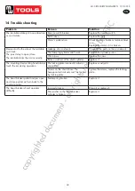
14. Trouble shooting table:
Problem
Reason
Solution
The turntable rotate just in one
direction or ca
n’t rotate
.
Reverse Switch broken
Replace the Reverse Switch
Belt broken
Replace the belt
The
Motor’s malfunction
Check the motor cable or terminal
block wire;
Replace the motor if it was
broken.
Demount or fix the wheel, the
turntable can’t lock
(spin with
wheel);
The jaws delay to open/close;
The turntable locks the rim
incorrectly.
Leakage of Air network
Check all the parts on the air
network.
The clamping c
ylinder can’t work
.
Replace the cylinder piston.
Worn jaws
Replace the jaws.
Broken washers of the chuck cylinder
Replace it.
The mounting/demounting head
always touch the rim during
operation.
The locking plate incorrectly adjust or
unqualified.
Replace or adjust it.
Screws on the chuck loose; the
Hexagonal Vertical Arm
can’t be
locked by Locking Plate
Tighten the screws; replace the
Locking Plate.
The Bead Breaker Pedal and
Jaw open and close Pedal
can’t
turn back to the original
position.
Pedal spring broken
Replace it.
The Bead Breaker shovel
operates difficultly.
Jammed silencer
Clean it or replace it.
The washer on the Bead Breaker
cylinder is broken.
Replace it.
Fig 18
.1211 . V201301
- 8 -
Note: In order to achieve the reliability of jaws and Bead Breaker shovel, operate as follows to keep their valves
clean
:
1. Remove the left side cover of the machine body by unscrewing the two screws;
2. Loosen the valve Muffler (A) which belong to Jaws open and close Pedal and Bead Breaker Pedal;
(Fig 18)
3. Clean the mufflers with compressed air, please replace it referring to the spare parts list if it is damaged.
(Fig 18)
Fig 16 Fig 17
14. Trouble shooting table:
Problem
Reason
Solution
The turntable rotate just in one
direction or ca
n’t rotate
.
Reverse Switch broken
Replace the Reverse Switch
Belt broken
Replace the belt
The
Motor’s malfunction
Check the motor cable or terminal
block wire;
Replace the motor if it was
broken.
Demount or fix the wheel, the
turntable can’t lock
(spin with
wheel);
The jaws delay to open/close;
The turntable locks the rim
incorrectly.
Leakage of Air network
Check all the parts on the air
network.
The clamping c
ylinder can’t work
.
Replace the cylinder piston.
Worn jaws
Replace the jaws.
Broken washers of the chuck cylinder
Replace it.
The mounting/demounting head
always touch the rim during
operation.
The locking plate incorrectly adjust or
unqualified.
Replace or adjust it.
Screws on the chuck loose; the
Hexagonal Vertical Arm
can’t be
locked by Locking Plate
Tighten the screws; replace the
Locking Plate.
The Bead Breaker Pedal and
Jaw open and close Pedal
can’t
turn back to the original
position.
Pedal spring broken
Replace it.
The Bead Breaker shovel
operates difficultly.
Jammed silencer
Clean it or replace it.
The washer on the Bead Breaker
cylinder is broken.
Replace it.
Fig 18
.1211 . V201301
- 8 -
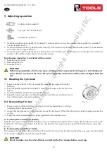
Note: In order to achieve the reliability of jaws and Bead Breaker shovel, operate as follows to keep their valves
clean
:
1. Remove the left side cover of the machine body by unscrewing the two screws;
2. Loosen the valve Muffler (A) which belong to Jaws open and close Pedal and Bead Breaker Pedal;
(Fig 18)
3. Clean the mufflers with compressed air, please replace it referring to the spare parts list if it is damaged.
(Fig 18)
Fig 16 Fig 17
14. Trouble shooting table:
Problem
Reason
Solution
The turntable rotate just in one
direction or ca
n’t rotate
.
Reverse Switch broken
Replace the Reverse Switch
Belt broken
Replace the belt
The
Motor’s malfunction
Check the motor cable or terminal
block wire;
Replace the motor if it was
broken.
Demount or fix the wheel, the
turntable can’t lock
(spin with
wheel);
The jaws delay to open/close;
The turntable locks the rim
incorrectly.
Leakage of Air network
Check all the parts on the air
network.
The clamping c
ylinder can’t work
.
Replace the cylinder piston.
Worn jaws
Replace the jaws.
Broken washers of the chuck cylinder
Replace it.
The mounting/demounting head
always touch the rim during
operation.
The locking plate incorrectly adjust or
unqualified.
Replace or adjust it.
Screws on the chuck loose; the
Hexagonal Vertical Arm
can’t be
locked by Locking Plate
Tighten the screws; replace the
Locking Plate.
The Bead Breaker Pedal and
Jaw open and close Pedal
can’t
turn back to the original
position.
Pedal spring broken
Replace it.
The Bead Breaker shovel
operates difficultly.
Jammed silencer
Clean it or replace it.
The washer on the Bead Breaker
cylinder is broken.
Replace it.
Fig 18
Fig. 16
Fig. 17
Fig. 18
copyrighted
document
- all
rights
reserved
by
FBC