background image

M1.3.BT200-BT200M.NLFREN   13112018

2

NL

AANDACHT!

Lees deze handleiding aandachtig voor het gebruik van de machine. Volg ook de veiligheidsvoorschriften en de 

onderhoudsinstructies. Bewaar deze handleiding in de nabijheid van de machine voor verdere raadpleging.

1  Voorwoord

Toepassingsgebied

De bandenwisselaar is speciaal ontworpen om banden op velgen demonteren/monteren.

Opgepast

Gebruik de machine alleen voor het doel waarvoor deze ontworpen werd.

De fabrikant aanvaardt geen aansprakelijkheid voor letstels of schade als gevolg van een oneigenlijk gebruik.

Belangrijke veiligheidsvoorschriften

Het gebruik van deze machine is uitsluitend bestemd voor getraind en gekwalificeerd professionals, die de handleiding 

gelezen hebben, of die voldoende ervaring hebben met soortgelijke machines. Elke wijziging zonder de toestemming van de 

fabrikant, of elk gebruik die niet voldoet aan de instructies van deze handleiding kan tot storingen of schade aan de machine 

leiden, en annuleert de fabrieksgarantie. Als een onderdeel om welke reden beschadigd is, moet het volgens de onderdelenlijst 

vervangen worden.

Inhoud

1  Voorwoord ..............................................................................................................................................................2
2  Waarschuwingslabels ...............................................................................................................................................3

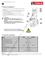
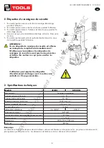
3  Technische specificaties

 .............................................................................................................................................3

4  Transport .................................................................................................................................................................4
5  Uitpakken en inspectie ..............................................................................................................................................4
6  Vereisten voor de installatieplaats ...............................................................................................................................4
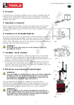
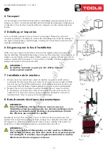
7  Installatie van de machine .........................................................................................................................................4
8  Elektrische en pneumatische aansluitingen ...................................................................................................................4
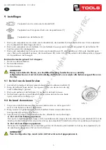
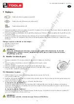
9  Instellingen ..............................................................................................................................................................5

9.1  De hiel van de band breken ...............................................................................................................................5

9.2  De band demonteren .........................................................................................................................................5

9.3  De band monteren ............................................................................................................................................6

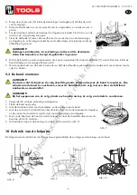
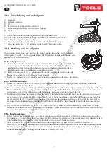
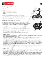
10  Gebruik van de hulparm .........................................................................................................................................6

10.1  Omschrijving van de hulparm ...........................................................................................................................7

10.2  Werking van de hulparm .................................................................................................................................7

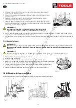
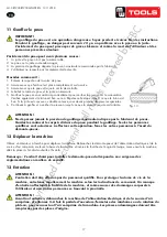
11  De band opblazen .................................................................................................................................................8
12  De machine verplaatsen ..........................................................................................................................................8
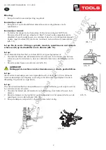
13  Onderhoud ...........................................................................................................................................................8
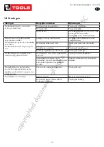
14  Storingen ............................................................................................................................................................10
15  Onderdelen .........................................................................................................................................................29
16  Schakelschema ....................................................................................................................................................38
17  Pneumatisch schema .............................................................................................................................................39
18  EG conformiteitsverklaring .....................................................................................................................................40

copyrighted 

document 

- all 

rights 

reserved 

by 

FBC

Summary of Contents for 754563092

Page 1: ...Bandenwisselaar D monte pneu Tyre changer P 02 Gelieve te lezen en voor later gebruik bewaren P 11 Veuillez lire et conserver pour consultation ult rieure P 20 Please read and keep for future referen...

Page 2: ...e wijziging zonder de toestemming van de fabrikant of elk gebruik die niet voldoet aan de instructies van deze handleiding kan tot storingen of schade aan de machine leiden en annuleert de fabrieksgar...

Page 3: ...eyond the scope of use on this machine without manufacturer s permission or do not according to the manual may cause the malfunction and damage to machine manufacturer can cancel warranty coverage for...

Page 4: ...optional device IT suffix version accessory details can be found at the IT suffix version exploded drawing 4 Transport When transporting the machine should be with original package and placed accordin...

Page 5: ...band breken 2 De band demonteren 3 De band monteren AANDACHT Draag nauwsluitende kleren een hoofdbescherming handschoenen en antislip veiligheidsschoenen Laat de lucht volledig uit de band en verwijd...

Page 6: ...voor het plaatsen en demonteren van de band 4 Laat de ene kant van de band boven het achterste deel van de demontage montagekop en de andere kant onder het voorste deel van de demontage montagekop 5 D...

Page 7: ...van de rol F Vergrendelingsschakelaar voor de rechter hulparm G Rol G De functie van de hendel van de hulparm werkt op volgende manier De hendel afb 8 D dient voor het stijgen en dalen van de rollen C...

Page 8: ...rm the operations do not allow other to operate or be near the tyre changer Fig 13 Afb 13 11 De band opblazen BELANGRIJK Een band opblazen is gevaarlijk Wees uiterst voorzichtig en volg de instructies...

Page 9: ...demounting head to rim please adjust Hexagonal Locking Plate refer to Fig 17 and adjust the X Fig 14 Fig 15 Afb 14 7 Please use forklift to move the machine Disconnect the tyre changer from the electr...

Page 10: ...de cilinder Spanklauwen versleten Vervang de spanklauwen Sluitringen gebroken op de cilinder Vervang de sluitringen De demontage montagekop raakt steeds de velg tijdens het werk De slotplaat is niet c...

Page 11: ...risation du fabricant et toute utilisation ne respectant pas les instructions de ce manuel peut entra ner un dysfonctionnement et des dommages la machine et annule la garantie du fabricant Si une pi c...

Page 12: ...ry Any changes and beyond the scope of use on this machine without manufacturer s permission or do not according to the manual may cause the malfunction and damage to machine manufacturer can cancel w...

Page 13: ...olumn C mount it on the machine body B by using the nut A through the bolt located on the machine body B If the column becomes loose after a period of using tight them immediately Otherwise the result...

Page 14: ...eu ATTENTION Portez des v tements pr s du corps un casque des gants et des chaussures de s curit antid rapantes Veillez vacuer compl tement l air du pneu et retirez toutes les masses d quilibrage pr s...

Page 15: ...ertical 2 Mettez le pneu sur la jante 3 Laissez le culbuteur en arri re pour placer comme pour d monter le pneu 4 Laissez un c t du pneu au dessus de la partie arri re de la t te de montage d montage...

Page 16: ...r fig 8 D sert lever et abaisser les rouleaux C G pour r gler la hauteur de montage d montage du pneu Montez le levier fig 8 D pour faire monter les rouleaux C G Abaissez le levier fig 8 D pour faire...

Page 17: ...trained persons are allowed to perform the operations do not allow other to operate or be near the tyre changer Fig 13 Fig 13 11 Gonfler le pneu IMPORTANT Le gonflage du pneu est une op ration danger...

Page 18: ...eet the requirement that 2 3mm from the bottom of Mounting demounting head to rim please adjust Hexagonal Locking Plate refer to Fig 17 and adjust the X Fig 14 Fig 15 Fig 14 7 Please use forklift to m...

Page 19: ...as Remplacez le piston du cylindre M choires us es Remplacez les m choires Rondelles cass es sur le cylindre Remplacez les rondelles La t te de montage d montage touche toujours la jante pendant le tr...

Page 20: ...erating similar machinery Any changes and beyond the scope of use on this machine without manufacturer s permission or do not according to the manual may cause the malfunction and damage to machine ma...

Page 21: ...scope of use on this machine without manufacturer s permission or do not according to the manual may cause the malfunction and damage to machine manufacturer can cancel warranty coverage for above If...

Page 22: ...ng circuit for prevent electric leakage And have operation range of ground for skid prevention 2 Unscrew the nut A on the cabinet body B as shown in Fig 3 Lift the column C mount it on the machine bod...

Page 23: ...hat gloves and skid proof shoes Ensure to exhaust the air in the tyre completely and remove all the wheel weights from the rim 1211 V201301 9 1 Breaking the tyre bead Ensure to exhaust the air in the...

Page 24: ...mounting arm 2 Put the tyre on the rim 3 Let the rocker arm back to place as demounting the tyre 4 Let one side of tyre down bead above the rear section of the mounting demounting head the other side...

Page 25: ...to approach rim Fig 11 Fig 8 Fig 9 Fig 10 Fig 12 1 Fig 12 10 1 Helping arm components A Swing arm B Small helping arm C Roller C D Raise fall roller handle F Locking switch for right helping arm G Ro...

Page 26: ...s are allowed to perform the operations do not allow other to operate or be near the tyre changer Fig 13 Fig 13 11 Inflating the tyre IMPORTANT It is very dangerous during inflating operation take car...

Page 27: ...o rim please adjust Hexagonal Locking Plate refer to Fig 17 and adjust the X Fig 14 Fig 15 Fig 14 7 Please use forklift to move the machine Disconnect the tyre changer from the electricity power suppl...

Page 28: ...work Replace the cylinder piston Worn jaws Replace the jaws Broken washers of the chuck cylinder Replace it The mounting demounting head always touch the rim during operation The locking plate incorre...

Page 29: ...B 014 080251 0 Outer hex bolt M8x25 7 B 010 080201 0 Hex socket head bolt M8 20 8 B 040 061412 1 Flat washer 6 14 1 2 200 9 C 000 001020 0 Rubber foot buffer 200 10 C 200 500000 0 Bead breaker buffer...

Page 30: ...Muffler 1 8 221 133 CX 221 160000 0 Vertical arm 221 134 C 228 520000 0 Vertical arm washer 135 3 CW 113 020003 0 Complete mount demount head 3 200 138 CX 200 150200 0 Mount demount head pulley 200 13...

Page 31: ...te square turntable 615 219 B 040 123030 1 Flat washer 12X30X3 200 220 CX 200 300000 0 Connection rod nut 221 221 CX 221 110100 0 Jaw slide guide without pin 221 222 C 221 100400 0 Threaded connection...

Page 32: ...er cylinder piston rod 329 B 014 080201 0 Outer hex bolt M8 20 311 S 005 168115 0 V seal 185X168X11 5 330 S 011 010808 0 Straight union1 8 8 200 312 C 200 050200 0 Bead breaker cylinder piston 200 334...

Page 33: ...33 M1 3 BT200 BT200M NLFREN 13112018 1211 V201301 200 480 c o p y r i g h t e d d o c u m e n t a l l r i g h t s r e s e r v e d b y F B C...

Page 34: ...441 B 010 080201 0 Hex socket head bolt M8 20 200 415 C 200 061500 0 Cam 442 S 012 010808 0 Quick Union1 8 8 200 416 C 200 810000 0 Cam washer 445 S 016 010808 2 Quick T union1 8 2 8 417 B 010 060201...

Page 35: ...020 0 Key washer 6 20 200 507 C 200 320400 0 Worm rod 508 S 040 006010 0 Bearing 6010 200 509 C 200 320200 0 Worm gear shaft 200 510 C 200 320100 0 Worm gear 200 511 CZ 200 320600 0 Worm gear shaft sp...

Page 36: ...00686 0 Tyre changer belt A 28 605 B 014 080651 0 Outer hex bolt M8X65 606 B 040 083030 1 Flat washer 8X30X3 607 80 S 063 008000 0 Capacitor 80 f 110V 607 50 S 063 005000 0 Capacitor 50 f 220V 608 B 0...

Page 37: ...0 Raise fall control valve F9816 S 023 010801 6 Muffler brass F9817 S 012 010406 0 Quick L union 1 4 6 F9818 S 013 104206 0 Quick T union 2X 6 4 F9820 S 017 010806 2 T union 1 8 2 6 F9823 C 007 18100...

Page 38: ...0M NLFREN 13112018 1211 V201301 16 Circuit diagram 17 Pneumatic drawing NL FR EN 16 Schakelschema 16 Sch ma lectrique 16 Circuit diagram c o p y r i g h t e d d o c u m e n t a l l r i g h t s r e s e...

Page 39: ...BT200 BT200M NLFREN 13112018 18 17 Pneumatic drawing NL FR EN 17 Pneumatisch schema 17 Sch ma pneumatique 17 Pneumatic drawing c o p y r i g h t e d d o c u m e n t a l l r i g h t s r e s e r v e d b...

Page 40: ...met inbegrip van deze betreffende het tijdstip van de verklaring der geldende veranderingen R pond aux normes g n rales caract ris es plus haut y compris celles dont la date correspond aux modificati...

Reviews:

Related manuals for 754563092