23
EN
M1.3.BT200-BT200M.NLFREN 13112018
.1211 . V201301
- 3
–
7. Position and installation:
1. Unscrew the nuts at the bottom, position the machine and calibrate it with the
horizontal rule. Mount the machine with all the screws and to ensure the machine is
stable. Make sure the system is equipped with a good grounding circuit for prevent
electric leakage. And have operation range of ground for skid prevention.
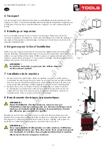
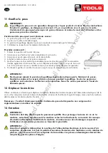
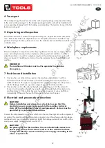
2. Unscrew the nut A on the cabinet body B as shown in
Fig 3
.
Lift the column C; mount it on the machine body B by using the nut A through the
bolt located on the machine body B. If the column becom
e
s loose after a period of
using, tight them immediately. Otherwise the result of damage to the tyre may
happen.
8. Electricity and Pneumatic connections:
Caution: Before installation and connection, check to be sure that the electricity
power supply corresponds to the machine technical data. All the installation of
electric and pneumatic devices must be operated by a professional electrician
.
Connect the compressed air connector which is on the machine right side with
compressed air system. The electric grid that the machine connects to must have
fuses protection device and good outer cover grounding protection. Install the
leakage automatic air switch on the maim power supply, leakage current is set at 30A
Caution: No power plug for this machine, the user should self-connect one power plug no less than 16A as well
as in line with the machine voltage. Or directly connect with the power supply according to the above
requirements
.
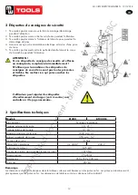
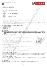
9. Adjusting operation:
Turntable Rotation Pedal (Z)
Bead Breaker Pedal (U)
Jaws open and close Pedal (V)
1)
Tread the Turntable Rotation Pedal (Z), Turntable (Y) clockwise rotation; Lift up the Turntable Rotation
Pedal (Z), Turntable (Y) counterclockwise rotation.
2)
Tread Bead Breaker Pedal (U), Bead Breaker shovel (R) close toward inside; release Bead Breaker Pedal (U),
Bead Breaker shovel (R) return to original position.
3)
Tread Jaws open and close Pedal (V), four clamps (G) on the turntable open; tread again, four clamps (G)
close. When the pedal is in the middle position, the four clamps stop moving.
Tyre changer operation is consisted of three parts:
1
)
Breaking the tyre bead
2
)
Demounting the tyre
3
)
Mounting the tyre
Caution: Before any operations, don
’
t wear loose clothing and wear protective hat, gloves, and skid-proof shoes.
Ensure to exhaust the air in the tyre completely, and remove all the wheel weights from the rim.
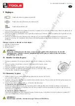
Fig 4
9 Adjusting operation
Turntable rotation pedal (Z)
Jaws open and close pedal (V)
Bead breaker pedal (U)
1.
Tread the turntable rotation pedal (Z), turntable (Y) clockwise rotation. Lift up the turntable rotation pedal (Z), turntable (Y)
counterclockwise rotation.
2.
Tread bead breaker pedal (U), bead breaker shovel (R) close toward inside. Release bead breaker pedal (U), bead breaker
shovel (R) return to original position.
3.
Tread jaws open and close pedal (V), four clamps (G) on the turntable open. Tread again, four clamps (G) close. When the
pedal is in the middle position, the four clamps stop moving.
Tyre changer operation is consisted of three parts:
1. Breaking the tyre bead.
2. Demounting the tyre.
3. Mounting the tyre.
CAUTION!
Before any operations, don’t wear loose clothing and wear protective hat, gloves, and skid-proof
shoes. Ensure to exhaust the air in the tyre completely, and remove all the wheel weights from the
rim.
.1211 . V201301
- 4 -
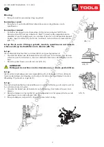
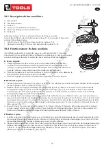
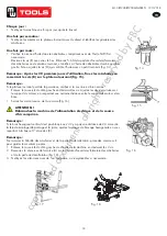
9.1. Breaking the tyre bead
:
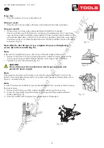
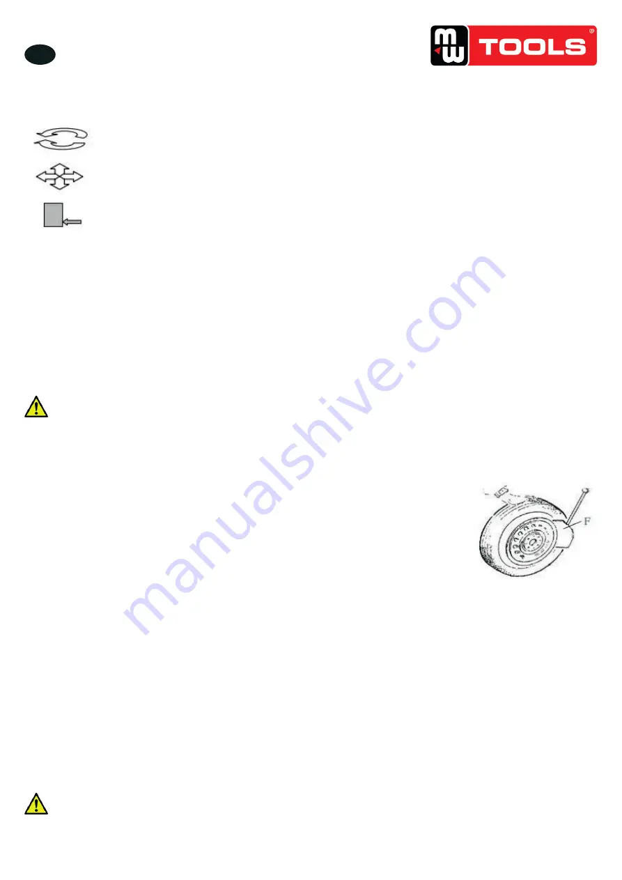
Ensure to exhaust the air in the tyre completely, place the tyre against the rubber
buffer (S). Bring the paddle against the bead about 10mm from the edge of the rim
shown as
Fig 5
. Tread Bead breaker Pedal (U) to push paddle into tyre. Repeat the
above operations on different positions around the tyre and both sides of tyre until tyre
bead is released completely.
9.2. Demounting the tyre :
Ensure to remove all the weights on the wheel rim and to exhaust the air in the tyre completely before this operation.
Apply lubricating grease (or similar lubricant) around the tyre bead. Without the lubricant may lead to badly wear and
tear on tyre.
Clamp the wheel methods shown as below regarded to the ruled dimension:
a- to clamp the wheel from outside:
Tread the Jaws open and close Pedal (V) halfway down to middle, positioning for the four clamps (G) by reference
scale on the Turntable (Y); put the tyre on turntable, hold the rim, and tread the Jaws open and close Pedal (V) until
the wheel is secured by the jaws.
b- to clamp the wheel from inside:
Positioning for the four clamps (G) and let them all closed. Put the tyre on the turntable and tread the Jaws open and
close Pedal (V) to open the clamps thereby lock the wheel in place.
Caution: Check to make sure the wheel firmly secured by the four clamps before next step
.
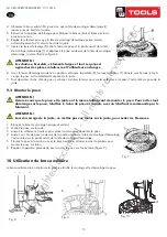
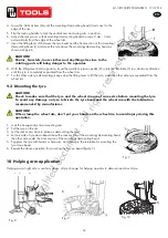
Lower the Vertical Arm (M) until the Mounting/demounting head (I)
rests next to the edge of the rim, flip the Locking Handle to lock the
Vertical Arm and Swing Arm in position, and also adjust the Rocker Arm
make Mounting/demounting head can raise 2mm-3mm automatically from
the edge of the wheel rim. Insert the Lifting Lever (T) between the tyre
bead and the front section of the mounting/demounting head (I), and move
the tyre above the mounting/demounting head as shown as
Fig 6
.
Caution: Chains, bracelets, loose clothes and anything else close to the rotating parts will bring danger to the
operator
.
With the Lifting Lever held in position, tread the Turntable Rotation Pedal (Z), rotate the Turntable (Y) in a
clockwise direction until the tyre is completely separated from the wheel rim.
For the other side tyre demounting, keep using the lifting lever to lift the tyre, make the other side tyre separated
from the wheel rim.
9.3. Mounting the tyre :
Caution: Check to make sure that the tyre and the wheel rim are of same size before mounting the tyre.
To avoid any damage on type, lubricate the tyre bead and the wheel rim with the lubrication recommended by
manufacturer. Put on the tyre and check the situation
.
Caution: When clamp the wheel rim, don't put your hands on the wheel rim to avoid injury during this
operation
.
Fig 6
Fig 5
Fig. 5
9.1 Breaking the tyre bead
1.
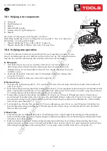
Ensure to exhaust the air in the tyre completely, place the tyre against the rubber
buffer (S).
2. Bring the paddle against the bead about 10 mm from the edge of the rim shown as
figure 5.
3. Tread bead breaker pedal (U) to push paddle into tyre.
4.
Repeat the above operations on different positions around the tyre and both sides of
tyre until tyre bead is released completely.
9.2 Demounting the tyre
1. Ensure to remove all the weights on the wheel rim and to exhaust the air in the tyre
completely before this operation.
2. Apply lubricating grease (or similar lubricant) around the tyre bead. Without the lubricant may lead to badly wear and tear
on tyre.
3.
Clamp the wheel methods shown as below regarded to the ruled dimension:
a. To clamp the wheel from outside:
Tread the Jaws open and close pedal (V) halfway down to middle, positioning for the four clamps (G) by reference scale on the
turntable (Y). Put the tyre on turntable, hold the rim, and tread the Jaws open and close pedal (V) until the wheel is secured by
the jaws.
b. To clamp the wheel from inside:
Positioning for the four clamps (G) and let them all closed. Put the tyre on the turntable and tread the jaws open and close Pedal
(V) to open the clamps thereby lock the wheel in place.
CAUTION!
Check to make sure the wheel firmly secured by the four clamps before next step.
copyrighted
document
- all
rights
reserved
by
FBC

