M1.3.BT200-BT200M.NLFREN 13112018
4
NL
7 Installatie van de machine
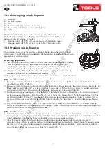
1. Draai de moeren aan de bodem los. Plaats de machine en zorg ervoor dat deze
horizontaal is. Monteer de machine met alle schroeven, en zorg ervoor dat deze
stabiel is. Let erop dat de elektrische installatie met een goede aarding uitgerust is, om
lekkages te voorkomen. De vloer moet antislip zijn.
2.
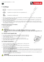
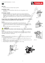
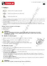
Draai de moer A op het frame B los, zoals in afbeelding 3 getoond. Til de kolom
C op. Monteer deze op het frame B door de moer A en de bout op het frame B te
gebruiken. Als de kolom na een tijdje losgaat, maak deze onmiddellijk opnieuw vast,
anders kan de band beschadigd worden.
8 Elektrische en pneumatische aansluitingen
AANDACHT!
Voor de installatie en de aansluiting, zorg ervoor dat de elektrische
installatie voldoet aan de technische gegevens van de machine.
De elektrische en pneumatische aansluitingen moeten door een
gekwalificeerde elektricien uitgevoerd worden.
Verbind de persluchtaansltuiting aan de rechterkant van de machine met uw
persluchtsysteem. Het elektriciteitsnet waaraan de machine aangesloten wordt, moet
met een stroomonderbreker en een aarding uitgerust zijn. Installeer de automatische
veiligheidsschakelaar op de hoofdvoeding. De lekstroom is op 30A vastgesteld.
AANDACHT!
Er is geen stekker op die machine. De gebruiker moet zelf een
stekker van tenminste 16 A installeren, die met de spanning van
de machine overeenkomt. Hij kan ook de machine rechtstreeks
aansluiten volgens bovenstaande vereisten.
.1211 . V201301
- 2 -
3. Technical data
External locking rim dimensions
10~21
"
Internal locking rim dimensions
12~24
"
Max. Wheel diameter
1040mm(41
"
)
Max. Wheel width
355mm(14
"
)
Working Pressure
8-10bar
Power supply
110V (1ph)/ 220V (1ph)/ 380V (3ph)
Optional Motor power
0.75/0.55/1.1 kw
Max. Rotating Torque (Turntable)
1078 Nm
Overall Dimension
96*76*93cm
Noise Level
75 Db
Remark
:
Rim dimensions defined at above table are based on the iron wheel rims. Aluminum rims are thicker than the
iron wheel rims, so here above rim dimensions are just for the reference.
Here above machine versions can be equipped with Rapid Tire Inflation Device (client optional device),
IT-suffix version, accessory details can be found at the IT-suffix version exploded drawing.
4. Transport:
When transporting, the machine should be with original package and placed according to the mark on the package.
For the already packaged machine should be handled with a corresponding tonnage forklift for loading and unloading.
The location to insert the fork feet shown as
Fig 1
5. Unpacking & Inspection:
Pull out the nail which is nailed on the plate with tip jaw; unpack the carton and plastic cover. Check and make sure
all parts shown on the spare parts list are included. If any parts are missing or broken, please do not use the machine
and contact the manufacturer or dealer ASAP.
Fig 1 Fig 2 Fig 3
6. Workplace requirements:
Choose workplace in compliance with safety regulations. Connect power supply and air source according to manual
and workplace must have good air condition; in order to make the machine run well, its workplace requires at least
clear space from each wall shown as
Fig 2
. If installing it outdoor, it must be protected by roof against rain and
sunshine.
Warning: the machine with motor must not be operated in explosive atmosphere
.
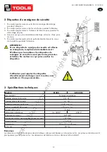
Afb. 1
.1211 . V201301
- 2 -
3. Technical data
External locking rim dimensions
10~21
"
Internal locking rim dimensions
12~24
"
Max. Wheel diameter
1040mm(41
"
)
Max. Wheel width
355mm(14
"
)
Working Pressure
8-10bar
Power supply
110V (1ph)/ 220V (1ph)/ 380V (3ph)
Optional Motor power
0.75/0.55/1.1 kw
Max. Rotating Torque (Turntable)
1078 Nm
Overall Dimension
96*76*93cm
Noise Level
75 Db
Remark
:
Rim dimensions defined at above table are based on the iron wheel rims. Aluminum rims are thicker than the
iron wheel rims, so here above rim dimensions are just for the reference.
Here above machine versions can be equipped with Rapid Tire Inflation Device (client optional device),
IT-suffix version, accessory details can be found at the IT-suffix version exploded drawing.
4. Transport:
When transporting, the machine should be with original package and placed according to the mark on the package.
For the already packaged machine should be handled with a corresponding tonnage forklift for loading and unloading.
The location to insert the fork feet shown as
Fig 1
5. Unpacking & Inspection:
Pull out the nail which is nailed on the plate with tip jaw; unpack the carton and plastic cover. Check and make sure
all parts shown on the spare parts list are included. If any parts are missing or broken, please do not use the machine
and contact the manufacturer or dealer ASAP.
Fig 1 Fig 2 Fig 3
6. Workplace requirements:
Choose workplace in compliance with safety regulations. Connect power supply and air source according to manual
and workplace must have good air condition; in order to make the machine run well, its workplace requires at least
clear space from each wall shown as
Fig 2
. If installing it outdoor, it must be protected by roof against rain and
sunshine.
Warning: the machine with motor must not be operated in explosive atmosphere
.
Afb. 2
.1211 . V201301
- 2 -
3. Technical data
External locking rim dimensions
10~21
"
Internal locking rim dimensions
12~24
"
Max. Wheel diameter
1040mm(41
"
)
Max. Wheel width
355mm(14
"
)
Working Pressure
8-10bar
Power supply
110V (1ph)/ 220V (1ph)/ 380V (3ph)
Optional Motor power
0.75/0.55/1.1 kw
Max. Rotating Torque (Turntable)
1078 Nm
Overall Dimension
96*76*93cm
Noise Level
75 Db
Remark
:
Rim dimensions defined at above table are based on the iron wheel rims. Aluminum rims are thicker than the
iron wheel rims, so here above rim dimensions are just for the reference.
Here above machine versions can be equipped with Rapid Tire Inflation Device (client optional device),
IT-suffix version, accessory details can be found at the IT-suffix version exploded drawing.
4. Transport:
When transporting, the machine should be with original package and placed according to the mark on the package.
For the already packaged machine should be handled with a corresponding tonnage forklift for loading and unloading.
The location to insert the fork feet shown as
Fig 1
5. Unpacking & Inspection:
Pull out the nail which is nailed on the plate with tip jaw; unpack the carton and plastic cover. Check and make sure
all parts shown on the spare parts list are included. If any parts are missing or broken, please do not use the machine
and contact the manufacturer or dealer ASAP.
Fig 1 Fig 2 Fig 3
6. Workplace requirements:
Choose workplace in compliance with safety regulations. Connect power supply and air source according to manual
and workplace must have good air condition; in order to make the machine run well, its workplace requires at least
clear space from each wall shown as
Fig 2
. If installing it outdoor, it must be protected by roof against rain and
sunshine.
Warning: the machine with motor must not be operated in explosive atmosphere
.
Afb. 3
.1211 . V201301
- 3
–
7. Position and installation:
1. Unscrew the nuts at the bottom, position the machine and calibrate it with the
horizontal rule. Mount the machine with all the screws and to ensure the machine is
stable. Make sure the system is equipped with a good grounding circuit for prevent
electric leakage. And have operation range of ground for skid prevention.
2. Unscrew the nut A on the cabinet body B as shown in
Fig 3
.
Lift the column C; mount it on the machine body B by using the nut A through the
bolt located on the machine body B. If the column becom
e
s loose after a period of
using, tight them immediately. Otherwise the result of damage to the tyre may
happen.
8. Electricity and Pneumatic connections:
Caution: Before installation and connection, check to be sure that the electricity
power supply corresponds to the machine technical data. All the installation of
electric and pneumatic devices must be operated by a professional electrician
.
Connect the compressed air connector which is on the machine right side with
compressed air system. The electric grid that the machine connects to must have
fuses protection device and good outer cover grounding protection. Install the
leakage automatic air switch on the maim power supply, leakage current is set at 30A
Caution: No power plug for this machine, the user should self-connect one power plug no less than 16A as well
as in line with the machine voltage. Or directly connect with the power supply according to the above
requirements
.
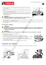
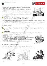
9. Adjusting operation:
Turntable Rotation Pedal (Z)
Bead Breaker Pedal (U)
Jaws open and close Pedal (V)
1)
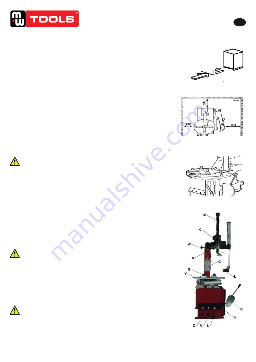
Tread the Turntable Rotation Pedal (Z), Turntable (Y) clockwise rotation; Lift up the Turntable Rotation
Pedal (Z), Turntable (Y) counterclockwise rotation.
2)
Tread Bead Breaker Pedal (U), Bead Breaker shovel (R) close toward inside; release Bead Breaker Pedal (U),
Bead Breaker shovel (R) return to original position.
3)
Tread Jaws open and close Pedal (V), four clamps (G) on the turntable open; tread again, four clamps (G)
close. When the pedal is in the middle position, the four clamps stop moving.
Tyre changer operation is consisted of three parts:
1
)
Breaking the tyre bead
2
)
Demounting the tyre
3
)
Mounting the tyre
Caution: Before any operations, don
’
t wear loose clothing and wear protective hat, gloves, and skid-proof shoes.
Ensure to exhaust the air in the tyre completely, and remove all the wheel weights from the rim.
Fig 4
Afb. 4
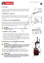
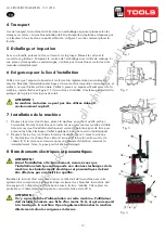
4 Transport
De machine moet in de originele verpakking vervoerd worden, en geplaatst volgens de
markering op de kist. De verpakte machine moet vervoerd, verplaatst en neergelegd
worden door een vorkheftruck met voldoende capaciteit. Afbeelding 1 toont hoe de vork
geplaatst moet worden.
5 Uitpakken en inspectie
Met een tang, verwijder de spijker van de plaat. Verwijder het karton en het kunststof
deksel. Vergelijk de inhoud van de verpakking met de paklijst. Als een onderdeel
ontbreekt of beschadigd is, gebruik de machine niet en neem onmiddellijk contact op met
uw verdeler.
6 Vereisten voor de installatieplaats
Zorg ervoor dat de werkruimte in overeenstemming is met de veiligheidsvoorschriften. Sluit
de elektrische voeding en de persluchtbron volgens de instructies, en zorg ervoor dat de
werkplaats goed geventileerd wordt. Maak zeker dat er voldoende ruimte is rondom de
machine, zoals in afbeelding 2 getoond. Als de machine buiten geïnstalleerd wordt, moet
deze tegen regen en zonlicht beschermd worden.
AANDACHT!
De machine met motor mag niet in een explosieve omgeving
geïnstalleerd worden.
copyrighted
document
- all
rights
reserved
by
FBC


