


M1.3.BT200-BT200M.NLFREN 13112018
6
NL
8.
Met de hefhendel in positie vastgehouden, druk op de voetpedaal (Z), draai de draaitafel (Y) met de klok mee totdat de
band volledig van de velg gescheiden wordt.
9.
Om de andere kant van de band te demonteren, blijf de hefhendel te gebruiken om de andere kant van de band van de
velg te scheiden.
9.3 De band monteren
AANDACHT!
Controleer dat de band en de velg dezelfde grootte hebben alvorens de band te monteren. Om
schade aan de band te voorkomen, smeer de bandhiel en de velg met een door de fabrikant
aanbevolen smeermiddel.
AANDACHT!
Bij het opspannen van de velg, plaats uw handen niet op de velg, om letsels te voorkomen.
4. Breng de verticale arm (M) totdat de demontage-/montagekop (I) dichtbij de rand
van de velg ligt.
5.
Draai de klemhendel om, om de verticale arm te vergrendelen, en zwenk de arm in
positie.
6. Pas de tuimelaar zodat de demontage-/montagekop automatisch tot 2-3 mm van de
rand van de velg omhoog kan gaan.
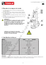
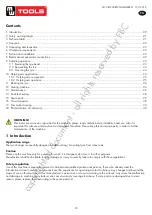
7. Steek de hefhendel (T) tussen de bandhiel en de voorste deel van de demontage-/
montagekop (I), en beweeg de band boven de demontage-/montagekop, zoals op
afbeelding 6 getoond.
AANDACHT!
Kettingen, armbanden, losse kleding en alles wat de draaiende
delen kan benaderen, brengt de gebruiker in gevaar.
.1211 . V201301
- 4 -
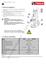
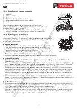
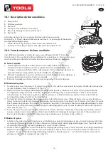
9.1. Breaking the tyre bead
:
Ensure to exhaust the air in the tyre completely, place the tyre against the rubber
buffer (S). Bring the paddle against the bead about 10mm from the edge of the rim
shown as
Fig 5
. Tread Bead breaker Pedal (U) to push paddle into tyre. Repeat the
above operations on different positions around the tyre and both sides of tyre until tyre
bead is released completely.
9.2. Demounting the tyre :
Ensure to remove all the weights on the wheel rim and to exhaust the air in the tyre completely before this operation.
Apply lubricating grease (or similar lubricant) around the tyre bead. Without the lubricant may lead to badly wear and
tear on tyre.
Clamp the wheel methods shown as below regarded to the ruled dimension:
a- to clamp the wheel from outside:
Tread the Jaws open and close Pedal (V) halfway down to middle, positioning for the four clamps (G) by reference
scale on the Turntable (Y); put the tyre on turntable, hold the rim, and tread the Jaws open and close Pedal (V) until
the wheel is secured by the jaws.
b- to clamp the wheel from inside:
Positioning for the four clamps (G) and let them all closed. Put the tyre on the turntable and tread the Jaws open and
close Pedal (V) to open the clamps thereby lock the wheel in place.
Caution: Check to make sure the wheel firmly secured by the four clamps before next step
.
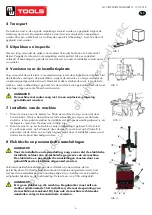
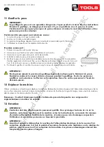
Lower the Vertical Arm (M) until the Mounting/demounting head (I)
rests next to the edge of the rim, flip the Locking Handle to lock the
Vertical Arm and Swing Arm in position, and also adjust the Rocker Arm
make Mounting/demounting head can raise 2mm-3mm automatically from
the edge of the wheel rim. Insert the Lifting Lever (T) between the tyre
bead and the front section of the mounting/demounting head (I), and move
the tyre above the mounting/demounting head as shown as
Fig 6
.
Caution: Chains, bracelets, loose clothes and anything else close to the rotating parts will bring danger to the
operator
.
With the Lifting Lever held in position, tread the Turntable Rotation Pedal (Z), rotate the Turntable (Y) in a
clockwise direction until the tyre is completely separated from the wheel rim.
For the other side tyre demounting, keep using the lifting lever to lift the tyre, make the other side tyre separated
from the wheel rim.
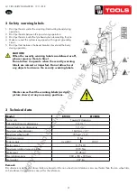
9.3. Mounting the tyre :
Caution: Check to make sure that the tyre and the wheel rim are of same size before mounting the tyre.
To avoid any damage on type, lubricate the tyre bead and the wheel rim with the lubrication recommended by
manufacturer. Put on the tyre and check the situation
.
Caution: When clamp the wheel rim, don't put your hands on the wheel rim to avoid injury during this
operation
.
Fig 6
Fig 5
Afb. 6
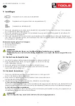
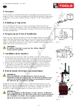
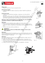
1. Vergrendel de verticale zeshoekige montagearm.
2. Plaats de band op de velg.
3. Laat de tuimelaar achter voor het plaatsen en demonteren van de band.
4.
Laat de ene kant van de band boven het achterste deel van de demontage-/montagekop,
en de andere kant onder het voorste deel van de demontage-/montagekop.
5.
Druk op de band met de hand of met de hulparm, en laat de draaitafel draaien om de
band op de hiel te monteren.
6. Herhaal deze stap om de band op de andere hiel te monteren (afb. 7).
.1211 . V201301
- 5
–
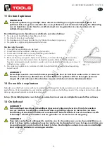
Lock the Hexagonal Vertical Mounting Arm, put the tyre on the rim, let
the Rocker Arm back to place as demounting the tyre. And let one side of
tyre down bead above the rear section of the Mounting/demounting head, the
other side under the front section of the Mounting/demounting head.
Suppress the trye with hands or help arm, and then spin the turntable for
mounting the tyre down bead.
Repeat the above operation for mounting the tyre up bead.
(Fig 7)
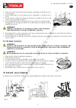
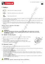
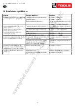
10. Helping arm application:
Helping arm at right side is auxiliary device of tyre changer for helping operator to demount and mount tyre.
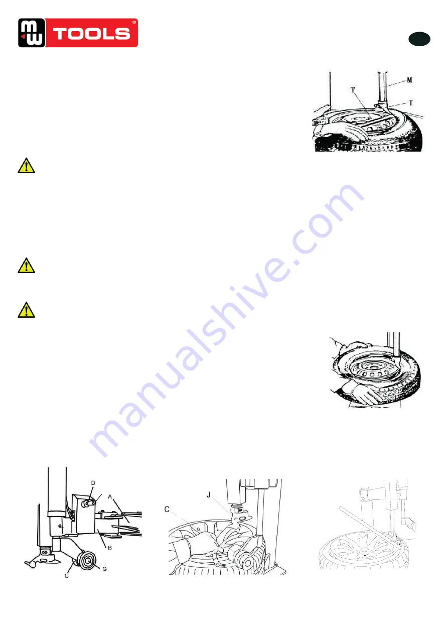
10.1 098 Help Arm Components
Each components of helping arm device are introduced as follows:
A- Swing arm B- Small helping arm
C- Roller C D- Raise-fall roller handle
F- Locking switch for right helping arm
G- Roller G
The function of helping arm control handle is as follows:
Roller lifting handle (D, Fig 8) is for lifting and lowering roller C
、
G so as to adjust
tyre demounting / mounting vertical height. Operate handle
(
D, Fig 8 ) up, then roller
C
、
G goes up
;
Operate handle
(
D, Fig 8 )down
,
then roller C
、
G goes down.
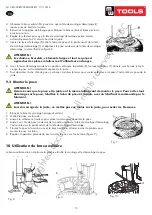
10.2 098 Help Arm Operation
It is difficult to demount and mount big and flat profile tyre. If operation is proper, it is very easy to use helping arm
device to demount and mount tyre from rim. The helping arm device may also be used
when demounting and mounting normal tyre with resistance.
a.
Clamp rim
Firstly, press both side tyre loose as per operation instruction in user’s manual. Force
of demounting and mounting is big when helping arm device is used. And rim may be
damaged easily. It is recommended that to clamp rim from outside
(
jaw protector may be
installed on jaws
)
. Tread relevant pedal to make jaws open to clamp edge of rim, move
helping arm’s rotary arm to far
-end. Put on tyre, tread relevant pedal to make jaws close
and to approach rim
Fig 11
Fig 8
Fig 9
Fig 10
F
Fig 12
1
Fig 7
Afb. 7
.1211 . V201301
- 5
–
Lock the Hexagonal Vertical Mounting Arm, put the tyre on the rim, let
the Rocker Arm back to place as demounting the tyre. And let one side of
tyre down bead above the rear section of the Mounting/demounting head, the
other side under the front section of the Mounting/demounting head.
Suppress the trye with hands or help arm, and then spin the turntable for
mounting the tyre down bead.
Repeat the above operation for mounting the tyre up bead.
(Fig 7)
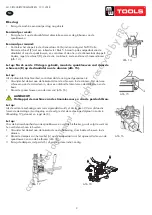
10. Helping arm application:
Helping arm at right side is auxiliary device of tyre changer for helping operator to demount and mount tyre.
10.1 098 Help Arm Components
Each components of helping arm device are introduced as follows:
A- Swing arm B- Small helping arm
C- Roller C D- Raise-fall roller handle
F- Locking switch for right helping arm
G- Roller G
The function of helping arm control handle is as follows:
Roller lifting handle (D, Fig 8) is for lifting and lowering roller C
、
G so as to adjust
tyre demounting / mounting vertical height. Operate handle
(
D, Fig 8 ) up, then roller
C
、
G goes up
;
Operate handle
(
D, Fig 8 )down
,
then roller C
、
G goes down.
10.2 098 Help Arm Operation
It is difficult to demount and mount big and flat profile tyre. If operation is proper, it is very easy to use helping arm
device to demount and mount tyre from rim. The helping arm device may also be used
when demounting and mounting normal tyre with resistance.
a.
Clamp rim
Firstly, press both side tyre loose as per operation instruction in user’s manual. Force
of demounting and mounting is big when helping arm device is used. And rim may be
damaged easily. It is recommended that to clamp rim from outside
(
jaw protector may be
installed on jaws
)
. Tread relevant pedal to make jaws open to clamp edge of rim, move
helping arm’s rotary arm to far
-end. Put on tyre, tread relevant pedal to make jaws close
and to approach rim
Fig 11
Fig 8
Fig 9
Fig 10
F
Fig 12
1
Fig 7
Afb. 8
.1211 . V201301
- 5
–
Lock the Hexagonal Vertical Mounting Arm, put the tyre on the rim, let
the Rocker Arm back to place as demounting the tyre. And let one side of
tyre down bead above the rear section of the Mounting/demounting head, the
other side under the front section of the Mounting/demounting head.
Suppress the trye with hands or help arm, and then spin the turntable for
mounting the tyre down bead.
Repeat the above operation for mounting the tyre up bead.
(Fig 7)
10. Helping arm application:
Helping arm at right side is auxiliary device of tyre changer for helping operator to demount and mount tyre.
10.1 098 Help Arm Components
Each components of helping arm device are introduced as follows:
A- Swing arm B- Small helping arm
C- Roller C D- Raise-fall roller handle
F- Locking switch for right helping arm
G- Roller G
The function of helping arm control handle is as follows:
Roller lifting handle (D, Fig 8) is for lifting and lowering roller C
、
G so as to adjust
tyre demounting / mounting vertical height. Operate handle
(
D, Fig 8 ) up, then roller
C
、
G goes up
;
Operate handle
(
D, Fig 8 )down
,
then roller C
、
G goes down.
10.2 098 Help Arm Operation
It is difficult to demount and mount big and flat profile tyre. If operation is proper, it is very easy to use helping arm
device to demount and mount tyre from rim. The helping arm device may also be used
when demounting and mounting normal tyre with resistance.
a.
Clamp rim
Firstly, press both side tyre loose as per operation instruction in user’s manual. Force
of demounting and mounting is big when helping arm device is used. And rim may be
damaged easily. It is recommended that to clamp rim from outside
(
jaw protector may be
installed on jaws
)
. Tread relevant pedal to make jaws open to clamp edge of rim, move
helping arm’s rotary arm to far
-end. Put on tyre, tread relevant pedal to make jaws close
and to approach rim
Fig 11
Fig 8
Fig 9
Fig 10
F
Fig 12
1
Fig 7
Afb. 9
N
.1211 . V201301
- 5
–
Lock the Hexagonal Vertical Mounting Arm, put the tyre on the rim, let
the Rocker Arm back to place as demounting the tyre. And let one side of
tyre down bead above the rear section of the Mounting/demounting head, the
other side under the front section of the Mounting/demounting head.
Suppress the trye with hands or help arm, and then spin the turntable for
mounting the tyre down bead.
Repeat the above operation for mounting the tyre up bead.
(Fig 7)
10. Helping arm application:
Helping arm at right side is auxiliary device of tyre changer for helping operator to demount and mount tyre.
10.1 098 Help Arm Components
Each components of helping arm device are introduced as follows:
A- Swing arm B- Small helping arm
C- Roller C D- Raise-fall roller handle
F- Locking switch for right helping arm
G- Roller G
The function of helping arm control handle is as follows:
Roller lifting handle (D, Fig 8) is for lifting and lowering roller C
、
G so as to adjust
tyre demounting / mounting vertical height. Operate handle
(
D, Fig 8 ) up, then roller
C
、
G goes up
;
Operate handle
(
D, Fig 8 )down
,
then roller C
、
G goes down.
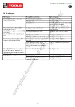
10.2 098 Help Arm Operation
It is difficult to demount and mount big and flat profile tyre. If operation is proper, it is very easy to use helping arm
device to demount and mount tyre from rim. The helping arm device may also be used
when demounting and mounting normal tyre with resistance.
a.
Clamp rim
Firstly, press both side tyre loose as per operation instruction in user’s manual. Force
of demounting and mounting is big when helping arm device is used. And rim may be
damaged easily. It is recommended that to clamp rim from outside
(
jaw protector may be
installed on jaws
)
. Tread relevant pedal to make jaws open to clamp edge of rim, move
helping arm’s rotary arm to far
-end. Put on tyre, tread relevant pedal to make jaws close
and to approach rim
Fig 11
Fig 8
Fig 9
Fig 10
F
Fig 12
1
Fig 7
Afb. 10
10 Gebruik van de hulparm
De hulparm aan de rechterkant van de machine vergemakkelijkt de montage en demontage van de band.
copyrighted
document
- all
rights
reserved
by
FBC


