


M1.3.BT200-BT200M.NLFREN 13112018
7
NL
.1211 . V201301
- 5
–
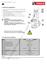
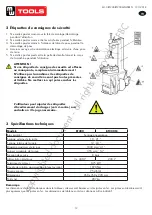
Lock the Hexagonal Vertical Mounting Arm, put the tyre on the rim, let
the Rocker Arm back to place as demounting the tyre. And let one side of
tyre down bead above the rear section of the Mounting/demounting head, the
other side under the front section of the Mounting/demounting head.
Suppress the trye with hands or help arm, and then spin the turntable for
mounting the tyre down bead.
Repeat the above operation for mounting the tyre up bead.
(Fig 7)
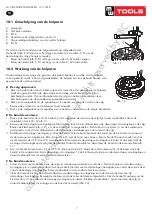
10. Helping arm application:
Helping arm at right side is auxiliary device of tyre changer for helping operator to demount and mount tyre.
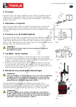
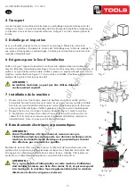
10.1 098 Help Arm Components
Each components of helping arm device are introduced as follows:
A- Swing arm B- Small helping arm
C- Roller C D- Raise-fall roller handle
F- Locking switch for right helping arm
G- Roller G
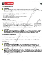
The function of helping arm control handle is as follows:
Roller lifting handle (D, Fig 8) is for lifting and lowering roller C
、
G so as to adjust
tyre demounting / mounting vertical height. Operate handle
(
D, Fig 8 ) up, then roller
C
、
G goes up
;
Operate handle
(
D, Fig 8 )down
,
then roller C
、
G goes down.
10.2 098 Help Arm Operation
It is difficult to demount and mount big and flat profile tyre. If operation is proper, it is very easy to use helping arm
device to demount and mount tyre from rim. The helping arm device may also be used
when demounting and mounting normal tyre with resistance.
a.
Clamp rim
Firstly, press both side tyre loose as per operation instruction in user’s manual. Force
of demounting and mounting is big when helping arm device is used. And rim may be
damaged easily. It is recommended that to clamp rim from outside
(
jaw protector may be
installed on jaws
)
. Tread relevant pedal to make jaws open to clamp edge of rim, move
helping arm’s rotary arm to far
-end. Put on tyre, tread relevant pedal to make jaws close
and to approach rim
Fig 11
Fig 8
Fig 9
Fig 10
F
Fig 12
1
Fig 7
Afb. 11
.1211 . V201301
- 5
–
Lock the Hexagonal Vertical Mounting Arm, put the tyre on the rim, let
the Rocker Arm back to place as demounting the tyre. And let one side of
tyre down bead above the rear section of the Mounting/demounting head, the
other side under the front section of the Mounting/demounting head.
Suppress the trye with hands or help arm, and then spin the turntable for
mounting the tyre down bead.
Repeat the above operation for mounting the tyre up bead.
(Fig 7)
10. Helping arm application:
Helping arm at right side is auxiliary device of tyre changer for helping operator to demount and mount tyre.
10.1 098 Help Arm Components
Each components of helping arm device are introduced as follows:
A- Swing arm B- Small helping arm
C- Roller C D- Raise-fall roller handle
F- Locking switch for right helping arm
G- Roller G
The function of helping arm control handle is as follows:
Roller lifting handle (D, Fig 8) is for lifting and lowering roller C
、
G so as to adjust
tyre demounting / mounting vertical height. Operate handle
(
D, Fig 8 ) up, then roller
C
、
G goes up
;
Operate handle
(
D, Fig 8 )down
,
then roller C
、
G goes down.
10.2 098 Help Arm Operation
It is difficult to demount and mount big and flat profile tyre. If operation is proper, it is very easy to use helping arm
device to demount and mount tyre from rim. The helping arm device may also be used
when demounting and mounting normal tyre with resistance.
a.
Clamp rim
Firstly, press both side tyre loose as per operation instruction in user’s manual. Force
of demounting and mounting is big when helping arm device is used. And rim may be
damaged easily. It is recommended that to clamp rim from outside
(
jaw protector may be
installed on jaws
)
. Tread relevant pedal to make jaws open to clamp edge of rim, move
helping arm’s rotary arm to far
-end. Put on tyre, tread relevant pedal to make jaws close
and to approach rim
Fig 11
Fig 8
Fig 9
Fig 10
F
Fig 12
1
Fig 7
Afb. 12
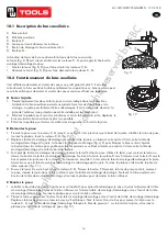
10.1 Omschrijving van de hulparm
A. Zwenkarm
B. Petit bras auxiliaire
C.
Rol C
D. Hendel voor het stijgen/dalen van de rol
F. Vergrendelingsschakelaar voor de rechter hulparm
G.
Rol G
De functie van de hendel van de hulparm werkt op volgende manier:
De hendel (afb. 8, D) dient voor het stijgen en dalen van de rollen C, G, om de
demontage-/montage hoogte te regelen.
•
Breng de hendel (afb. 8, D) omhoog, om de rollen C, G te laten stijgen.
•
Breng de hendel (afb. 8, D) omlaag, om de rollen C, G te laten dalen.
10.2 Werking van de hulparm
De demontage en montage van groot en vlak profiel banden is moeilijk. Als de hulparm
correct gebruikt wordt, is het veel gemakkelijker. De hulparm kan ook gebruikt worden voor
gewone banden met weerstand.
A De velg opspannen
1.
Druk op beide zijden van de band, volgens de instructies. Het gebruik van de hulparm
biedt een grote kracht bij de demontage en montage van de band. De velg kan
beschadigd worden. Het wordt aanbevolen de velg van buiten op te spannen (een
bescherming kan op de spanklauwen geïnstalleerd worden).
2.
Druk op de voetpedaal om de spanklauwen te openen, en span de rand van de velg.
Beweeg de zwenkarm van de hulparm zo ver mogelijk.
3. Druk op de voetpedaal op de spanklauwen te sluiten en de rand van de velg te benaderen.
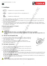
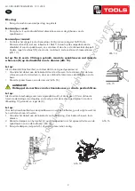
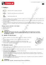
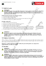
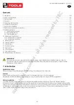
B De band demonteren
1.
Druk op de band met de rol C, G totdat hij 3 cm lager dan de rand van de velg ligt. Smeer de bandhiel, draai de
draaitafel, til de rol C, G (afb. 9).
2.
Beweeg de demontage-/montagekop dichtbij de velg, laat 2-3 mm afstand tussen de demontage-/montagekop en de velg.
Bedien de klemhendel (afb. 4, K), om de verticale arm te vergrendelen. Stel de bout in de kolom in, om de zwenkarm te
positioneren. Laat 2-3 mm afstand tussen de demontage-/montagekop en de rand van de velg.
3.
Dichtbij de demontage-/montagekop, steek de hendel N in de band. Gebruik de hendel om de hiel boven de knop van
de demontage-/montagekop te tillen. Draai de rol C met de hand naar binnen, trek de hendel D naar beneden en druk
op de velg met de rol C, door 3-5 mm afstand te laten tussen de demontage-/montagekop te laten. Maak zeker dat de
montage-/demontagekop de velg niet beschadigt. Draai de draaitafel en demonteer de band van de bovenste hiel (afb.
11).
4.
Duw de hendel D naar boven. Til de rol C, G. Druk op de knop F. Maak de rechter drukarm los, til de band, steek de
hendel in de onderste hiel bij de demontage-/montagekop. Til de hiel boven de knop van de demontage-/montagekop en
draai de draaitafel om de onderste hiel te demonteren.
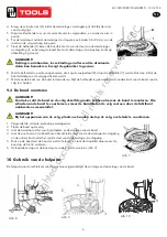
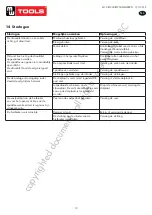
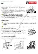
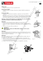
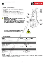
C De band monteren
1. Smeer de rand van de band en van de velg om schade aan de band te voorkomen. Stel de hoogte van de demontage-/
montagekop in, en plaat de onderste hiel op de achterste deel van de demontage-/montagekop en onder de voorste deel
van de demontage-/montagekop. Draai de draaitafel om de onderste hiel te monteren.
1. Plaat de bovenste hiel op de achterste deel van de demontage-/montagekop en onder de voorste deel van de
demontage-/montagekop. Beweeg de drukarm en maak zeker dat deze vergrendeld is. Trek de hendel D omlaag, om de
hiel met de rol C, G onder de demontage-/montagekop te duwen. Blokkeer de drukblok 1 op de rand van de velg, en
draai de draaitafel om de montage van de band af te werken (afb. 12).
copyrighted
document
- all
rights
reserved
by
FBC


