15
PPH75B - NLFREN - v1.1 - 29052017
FR
10
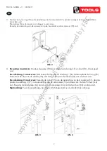
Figure 1
Assemble the nylon ring (71) to gauge fitting (51), then put the pressure gauge (50)
and twist tight. Remark: twist as tight as possible, otherwise it will be leak. Attach the
gauge fitting to the suitable upper cross beam and twist nut (52)
Figure 2
Pump assemble: attach the pump assy’ (53) to frame by using washer (15) and bolt
(54) and twist tight.
Hydraulic hose 1 assemble: dismantle the plug from Hydraulic hose 1 (57) then
assemble the o-ring(55), also dismantle the plug from ram assy’(46), connect the
Hydraulic hose 1 (56) to ram assy’(46) and twist tight.
Hydraulic hose 2 assemble: attach the o-ring (55) to gauge fitting (51), then put the
Hydraulic hose 2(57) into the gauge fitting (51) and twist tight, connect the PU pipe
(A-A). Attach the handle (64) to the pump pin by using bolt (65) and twist tight.
Remark: before assemble, open the breather valve first which is on the cylinder (pull
up the breather valve).
3. Assemblez la bague en nylon (72) au raccord du manomètre (51), placez ensuite le manomètre (50) et serrez.
Remarque: Serrez le plus possible pour éviter les fuites.
Fixez le raccord du manomètre sur le montant supérieur et serrez l’écrou (52).
4.
Assemblage de la pompe
: Fixez le corps de la pompe (53) au cadre en utilisant la rondelle (15) et le boulon
(54) et serrez.
Assemblage tuyau hydraulique 1
: Enlevez le bouchon du tuyau hydraulique 1 (57) et placez le joint torique
(55), enlevez le bouchon du piston (46), branchez le tuyau hydraulique 1 (56) au piston (46) et serrez.
Assemblage tuyaux hydraulique 2
: Fixez le joint torique (55) au raccord du manomètre (51), puis placez le
tuyau hydraulique 2 (57) dans le raccord du manomètre (51) et serres. Branchez le tuyau PU (A-A) . Fixez la poignée
(64) à la pompe en utilisant le boulon (66) et serrez.
Remarque
: Avant l’assemblage, ouvrez d’abord le reniflard sur le cylindre
(Tirez vers le haut).
11
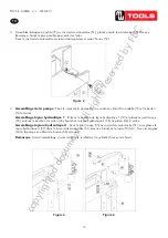
Figure3
Figure 4
Move the hand winch (12) to the outside of the post, then use bolt (02), washer (06),
lock washer (05), and nut (04) which were dismantled just now to twist tight and fix to
the relevant roller.
Figure 5
3.6 Commissioning the machine
Before the commissioning
Before the first use, please fix the machine to the floor by anchor bole. It must be
ensured that the standing surface of the machine site is firm and horizontal, and that
sufficient lighting is provided for.
Clean the machine thoroughly
Before first use of this product, pour a teaspoon of good quality, air tool lubricant into
the air supply inlet of the lift control valve, connect to air supply to air supply and
copyrighted
document
- all
rights
reserved
by
FBC


