background image

24

PPH75B - NLFREN - v1.1 - 29052017

EN

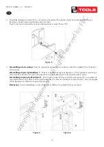
5.  Move the hand winch (12) to the outside of the post, then use bolt (02), washer (06), lock washer (05), and nut (04) 

which were dismantled just now to twist tight and fix to the relevant roller.


11 

Figure3


Figure 4

  Move the hand winch (12) to the outside of the post, then use bolt (02), washer (06), 

lock washer (05), and nut (04) which were dismantled just now to twist tight and fix to 
the relevant roller. 

Figure 5

3.6 Commissioning the machine   

Before the commissioning 

Before the first use, please fix the machine to the floor by anchor bole. It must be 

ensured that the standing surface of the machine site is firm and horizontal, and that 
sufficient lighting is provided for. 

  Clean the machine thoroughly   

  Before first use of this product, pour a teaspoon of good quality, air tool lubricant into 

the air supply inlet of the lift control valve, connect to air supply to air supply and 

3.5  Commissioning the machine

Before the commissioning

Before t

he first use, please fix the machine to the floor by anchor bolt. It must be ensured that the standing surface of the 

machine site is firm and horizontal, and that sufficient lighting is provided for. 

1.  Clean the machine thoroughly. 

2. 

Before first use of this product, pour a teaspoon of good quality, air tool lubricant into the air supply inlet of the lift 

control valve, connect to air supply to air supply and operate for 3 seconds to evenly distribute lubricant. 

3.  Purge away air from the hydraulic system.  

- Manual operation system: open the release valve by turning it counterclockwise. Pump several full stokes to eliminate 

any air in the system.  

- Air operating system: open the release valve by turning it counterclockwise. Connect the quick coupler-male into 

the air supply hose quick coupler-female, then turn on the air valve with shield (61) letting the pump work for several 

times to eliminate any air in the system. 

4.  Check all parts and conditions, if there is any part broken, stop using it and contact your supplier immediately. 

4  Operation

1.  Ensure 

bed frame at proper position and lock the bed frame by pins (18) firmly.

2.  Place the heel block (32) on bed frame (31), then insert workpiece onto the heel block. 

Note

: The steel block must be used per pair, not by piece!


         The steel block can be used by both sides.

3. 

Close the release valve (P16) by turning it clockwise until it is firmly closed. 

4. 

Connect the air hose fitting (75) into the junction of air source, turn on the air valve (61) to let the pump work until 

serrated saddle (49) nears workpiece, then turn off the air valve.  

When air source is unavailable, pump the handle (64) until serrated saddle (49) nears workpiece. 

5.  Align workpiece and ram to ensure center loading. 

6.  Turn on air valve (or pump handle) to apply load onto workpiece (please see numeration in pressure gauge). 

7.  When work is done, turn off the air valve (or stop pumping handle), slowly and carefully remove load from 

workpiece by turning the release valve (P16) counterclockwise in small increments.(must turn with the small angle, the 

biggest is two circles) 

8.  Once ram has fully retracted, remove workpiece from bed frame. 

9. 

Disconnect the air inlet fitting from the air source. 

copyrighted 

document 

- all 

rights 

reserved 

by 

FBC

Summary of Contents for 757170075

Page 1: ...Presse d atelier hydraulique Hydraulic shop press P 02 Gelieve te lezen en voor later gebruik bewaren P 10 Veuillez lire et conserver pour consultation ult rieure P 18 Please read and keep for future...

Page 2: ...bestaande risico s Laat de pers door gekwalificeerd personeel onderhouden Houd de pers schoon voor betere en veilige prestaties De maximale capaciteit van de pers is 75 ton Overschrijd die capaciteit...

Page 3: ...nsten nummers in de nabijheid van de machine Voor het onderhoud van het hydraulische systeem moet u de druk van het systeem ontlasten Niemand mag aan de druk blootgesteld worden De bediener moet zich...

Page 4: ...s Eenheid Waarde 1 Capaciteit T 75 2 Koers mm 250 3 Druk in het hydraulische systeem MPa 59 92 4 Werkbereik mm 170 884 5 Interne luchtaansluiting NPT 1 4 6 Luchtdruk MPa 0 75 0 85 7 Bed grootte Breedt...

Page 5: ...g the machine please make sure to use the proper lifting equipment and follow the instructions as follows Hydraulic part 3 2 Working Area Conditions Users should provide enough space for the equipment...

Page 6: ...k washer 05 and nut 04 3 4 Installatie De machine moet ge nstalleerd en in gebruik genomen worden door gekwalificeerd personeel Alle wettelijke veiligheidsvoorschriften moeten nageleefd worden Verpakk...

Page 7: ...aansluiting van de manometer 51 plaats vervolgens de manometer 50 en draai deze vast Opmerking Draai stevig vast om lekkages te voorkomen Bevestig de aansluiting van de manometer op de bovenbalk en dr...

Page 8: ...edig om de lucht van het systeem te verwijderen Perslucht werkwijze open de aflaatklep door tegen de klok te draaien Sluit de mannelijke snelkoppeling aan met de vrouwelijke snelkoppeling van de lucht...

Page 9: ...overgeladen machine Controleer de luchtdruk en de capaciteit van de pers De perslucht motor is gebroken Vervang de perslucht motor Olie lekkage Beschadigde pakkingen Vervang de beschadigde pakkingen...

Page 10: ...qui concerne l installation l utilisation et l entretien de l quipement et consciente des risques qui y sont li s Faites entretenir la presse par du personnel qualifi Gardez la propre pour des perform...

Page 11: ...re utilis e N exposez pas la presse la pluie ou autres intemp ries Faites faires les r parations par du personnel qualifi et n utilisez que les pi ces de rechange d origine Installez des panneaux d av...

Page 12: ...ph re Non inflammable non corrosive et sans poussi re clairage ambiant 300 lux missions sonores 85 dB C 2 3 Partie m canique N Donn es Unit s Valeur 1 Capacit T 75 2 Course mm 250 3 Pression du syst m...

Page 13: ...ne please make sure to use the proper lifting equipment and follow the instructions as follows Hydraulic part 3 2 Working Area Conditions Users should provide enough space for the equipment and the en...

Page 14: ...06 lock washer 05 and nut 04 3 4 Installation La machine doit tre install e et mise en service par du personnel qualifi Les r gles de s curit doivent tre strictement respect es Conditions d emballage...

Page 15: ...nylon 72 au raccord du manom tre 51 placez ensuite le manom tre 50 et serrez Remarque Serrez le plus possible pour viter les fuites Fixez le raccord du manom tre sur le montant sup rieur et serrez l c...

Page 16: ...antihoraire Pompez plusieurs fois fond pour liminer l air du syst me Op ration avec air comprim ouvrez la valve de purge en tournant dans le sens antihoraire Connectez le raccord rapide m le du tuyau...

Page 17: ...isante et machine en surcharge Contr lez la pression d air et la capacit de la presse Moteur pneumatique cass Remplacez le moteur pneumatique Fuite d huile Joints endommag s Remplacez les joints endom...

Page 18: ...ices with the installation process operation and maintenance of this equipment and with all the hazards involved Use a qualified person to maintain the press in good condition Keep it clean for best a...

Page 19: ...n is on going Post a list with emergency phone numbers nearby the working area Before maintenance pressured parts in the machine you MUST release the pressure in the pressured system At the same time...

Page 20: ...tude The item should be installed at an altitude of maximum 1000 m Humidity Maximum 85 relative humidity at 40 without condensation Atmosphere Non flammable non corrosive and dust free Ambient light 3...

Page 21: ...eights and dimensions of this machine unit are shown on the label in clause 2 During moving the machine please make sure to use the proper lifting equipment and follow the instructions as follows Hydr...

Page 22: ...bolt 02 washer 06 lock washer 05 and nut 04 3 4 Installation The machine must only be installed and commissioned by qualified personnel All relevant safety regulations must be strictly adhered to Pack...

Page 23: ...nylon ring 72 to gauge fitting 51 then put the pressure gauge 50 and twist tight Remark twist as tight as possible otherwise it will be leak Attach the gauge fitting to the suitable upper cross beam...

Page 24: ...lve by turning it counterclockwise Pump several full stokes to eliminate any air in the system Air operating system open the release valve by turning it counterclockwise Connect the quick coupler male...

Page 25: ...tor is broken Replace the air motor Oil leaking Seal kits broken Replace the seal kits Screw parts loosed Tighten the screw parts 6 Maintenance Maintenance should be acted before daily working everyda...

Page 26: ...26 PPH75B NLFREN v1 1 29052017 NL FR EN 7 Onderdelen 7 Pi ces d tach es 7 Spare parts FRAME CH SSIS FRAME c o p y r i g h t e d d o c u m e n t a l l r i g h t s r e s e r v e d b y F B C...

Page 27: ...er 3 54 Bolt 3 17 Nut 3 55 O Ring 4 18 Pin 4 56 Hydraulic Hose 1 1 19 Circlip 8 57 Hydraulic Hose 2 1 20 Bushing 2 4 58 Oil Hose 1 21 Sleeve 2 59 Air Hose 1 22 Bolt 4 60 Screw 1 23 Lock Washer 4 61 Ai...

Page 28: ...28 PPH75B NLFREN v1 1 29052017 POMP POMPE PUMP c o p y r i g h t e d d o c u m e n t a l l r i g h t s r e s e r v e d b y F B C...

Page 29: ...1 Lock Washer 1 P40 Pin 1 P12 Screw 1 P41 Circlip 2 P13 Washer 1 P42 Pin 1 P14 Release Valve Seat 1 P43 Hand Press 1 P15 O Ring 1 P44 Copper Ring 1 P16 Release Valve 1 P45 Valve Plug 1 P17 Ball 1 P46...

Page 30: ...30 PPH75B NLFREN v1 1 29052017 PISTON RAM c o p y r i g h t e d d o c u m e n t a l l r i g h t s r e s e r v e d b y F B C...

Page 31: ...Ring 1 R08 Piston 1 R09 PTFE Ring 2 R10 O Ring 2 R11 Piston Head 1 R12 Valve Core 1 R13 Screw 1 R14 Nylon Ring 1 R15 Retaining Ring 1 R16 O Ring 1 R17 Nut 1 R18 Spring 1 R19 Cylinder 1 R20 Pin 1 R21...

Page 32: ...betreffende het tijdstip van de verklaring der geldende veranderingen R pond aux normes g n rales caract ris es plus haut y compris celles dont la date correspond aux modifications en vigueur Meets th...

Reviews: