PPH75B - NLFREN - v1.1 - 29052017
7
NL
10
Figure 1
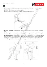
Assemble the nylon ring (71) to gauge fitting (51), then put the pressure gauge (50)
and twist tight. Remark: twist as tight as possible, otherwise it will be leak. Attach the
gauge fitting to the suitable upper cross beam and twist nut (52)
Figure 2
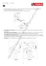
Pump assemble: attach the pump assy’ (53) to frame by using washer (15) and bolt
(54) and twist tight.
Hydraulic hose 1 assemble: dismantle the plug from Hydraulic hose 1 (57) then
assemble the o-ring(55), also dismantle the plug from ram assy’(46), connect the
Hydraulic hose 1 (56) to ram assy’(46) and twist tight.
Hydraulic hose 2 assemble: attach the o-ring (55) to gauge fitting (51), then put the
Hydraulic hose 2(57) into the gauge fitting (51) and twist tight, connect the PU pipe
(A-A). Attach the handle (64) to the pump pin by using bolt (65) and twist tight.
Remark: before assemble, open the breather valve first which is on the cylinder (pull
up the breather valve).
3. Monteer de nylon ring (72) op de aansluiting van de manometer (51), plaats vervolgens de manometer (50) en
draai deze vast.
Opmerking: Draai stevig vast, om lekkages te voorkomen.
Bevestig de aansluiting van de manometer op de bovenbalk en draai de moer (52) vast.
4.
De pomp monteren:
Monteer de pomp (53) door middel van de ring (15) en bout (54) , draai goed
vast.
De olieslang 1 monteren:
Demonteer de dop van de olieslang 1 (56), daarna plaats de o-ring (55).
Demonteer de dop van de cilinder (46), sluit slang 1 (56) aan de cilinder (46) aan en draai vast.
De olieslang 2 monteren:
Bevestig de o-ring (55) aan de aansluiting van de manometer (51), daarna
plaats de olieslang 2 (57) in de aansluiting van de manometer (51) en draai vast. Sluit de PU buis (A-A)
aan. Bevestig de handgreep (64) aan de pin van de pomp, door middel van bout (66) en draai vast.
Opmerking
: Voor de assemblage, open het ontluchtingsventiel op de cilinder (trek omhoog).
11
Figure3
Figure 4
Move the hand winch (12) to the outside of the post, then use bolt (02), washer (06),
lock washer (05), and nut (04) which were dismantled just now to twist tight and fix to
the relevant roller.
Figure 5
3.6 Commissioning the machine
Before the commissioning
Before the first use, please fix the machine to the floor by anchor bole. It must be
ensured that the standing surface of the machine site is firm and horizontal, and that
sufficient lighting is provided for.
Clean the machine thoroughly
Before first use of this product, pour a teaspoon of good quality, air tool lubricant into
the air supply inlet of the lift control valve, connect to air supply to air supply and
Afb 3
Afb 4
Afb 2
copyrighted
document
- all
rights
reserved
by
FBC


