36
M1.2.MIG160E-MIG200E.NLFREN 09102018
NL
FR
EN
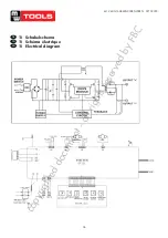
11 Schakelschema
11 Schéma électrique
11 Electrical diagram
N2190A SC-A0
8. ELECTRICAL SCHEMATIC DIAGRAM
Fig. 2
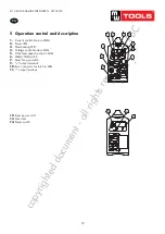
9. OPERATION CONTROL AND DESCRIPTION
1.
Current control knob in MMA
2.
Power LED
3.
Overheating LED
4.
Voltage control knob in MIG
5.
Wire feed speed control in MIG
6.
MMA/MIG switch
7.
Gas/No gas switch
8.
Socket for push-pull torch
9.
"+" output terminal
10.
Euro connector for torch in MIG
11.
"-" output terminal
11
10
9
8
7
1 2
3 4
5
6
Fig. 3
Hole 1:
Push-pull torch power source ”+”
Hole 2:
Push-pull torch power source ”-”
Hole 3~9:
Null
Fig. 4
Socket for push-pull torch power
source and torch trigger
10
N2
190A
SC
-A0
A
PPEN
D
IX
C
:W
IRI
N
G
DI
AG
R
AM
OF
COM
PL
ET
E M
A
CHI
NE
Thi
s produ
ct
i
s
be
ing
i
m
prov
ed
unc
ea
si
ngl
y,
s
o d
iff
ere
nc
es
m
ay
a
ppe
ar
in p
art
s
exc
ep
t f
or
func
tions
a
nd ope
ra
tion.
Tha
nk
s f
or unde
rs
ta
ndi
ng.
33
copyrighted
document
- all
rights
reserved
by
FBC

