


my!
WIND
Ltd.
Soola 1a
51013 Tartu, Estonia
Email: info@mywind.ee
Website: www.mywind.ee
14 |
P a g e 2 6 / 0 7 / 2 0 1 9
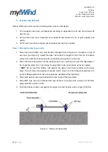
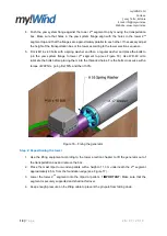
Step 6: Connecting the lifting equipment
1. Lift the gin-pole up into a vertical position as much as the connection cable allows it.
2. Take the cable end with the hook and connect it to a lifting equipment. A tractor or a car with
a winch can be used in order to achieve at least 3000 kg of pulling force (see Figure 11). If
you are using a car with a winch, make sure that the car has all the brakes applied at all times
and is anchored to a strong point. The winch on the car must have a functional brake.
! IMPORTANT:
Keep the lifting cable under pressure all the time to prevent the gin-pole from
falling down.
In this manual two different tower levelling techniques are presented. In
Step 8
of this chapter, a
technique with the simple sprit level is presented. In case you have acquired or your distributor
possesses ITS-2-45 dual axis inclinometer, please follow the guideline in
Annex 1
before proceeding
to
Step 7
and in that case skip
Step 8
.
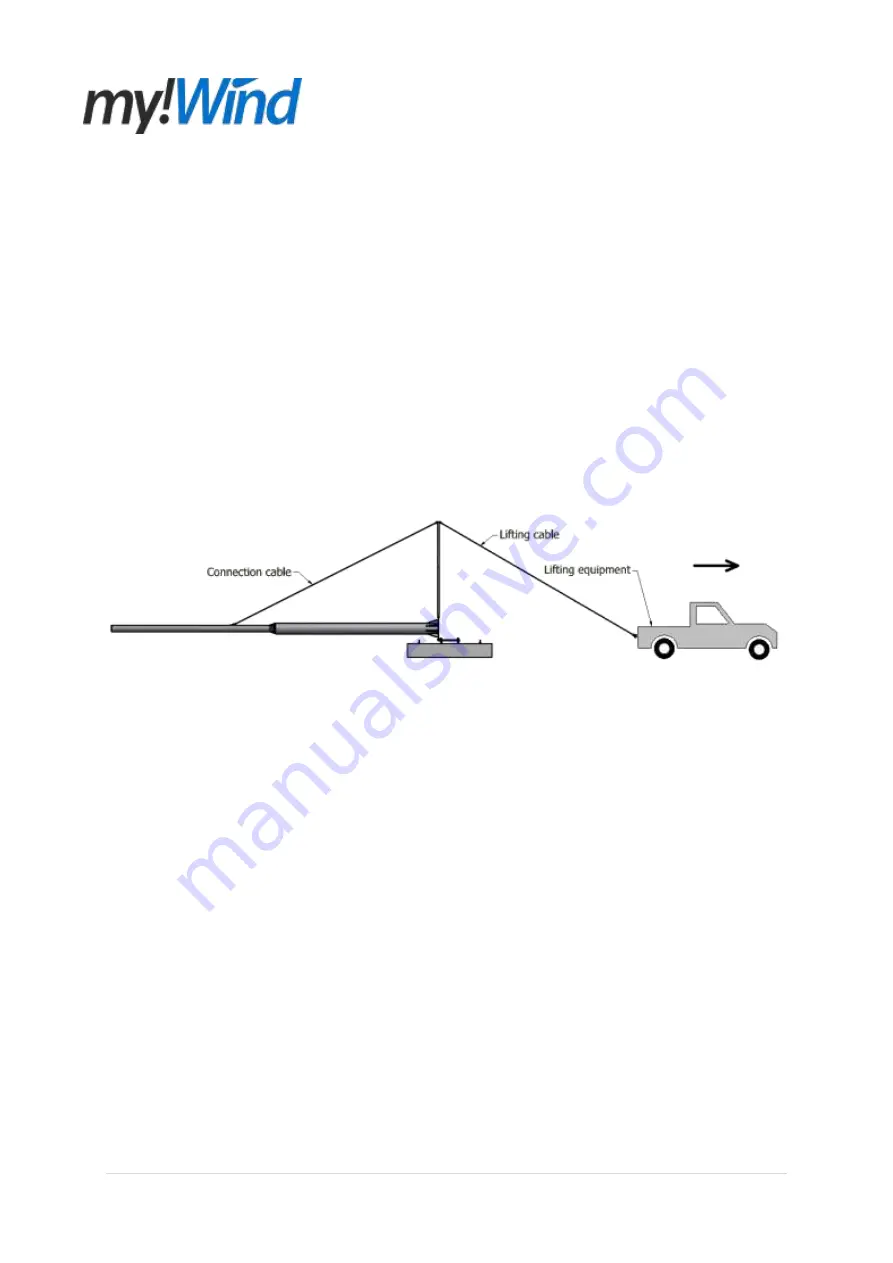
Figure 11
– Connecting the lifting equipment
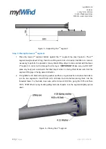
Step 7: Test lifting the tower
1. Check that all the tower segments are firmly connected together and to the base plate. Check
that the gin-pole is connected to the 1
st
segment. Check that all the shackles and cables are
firmly secured to the segments, gin-pole and lifting equipment. Clear all the uninvolved
persons from the area.
! IMPORTANT:
DO NOT raise the tower with a turbine until you have
raised and lowered the tower without a turbine. Never stand near or under the tower or gin-
pole when raising or lowering the tower.
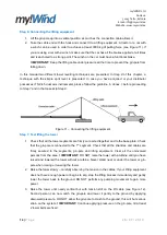
2. Raise the tower slowly
– carefully observing the tension in the cables. If your lifting equipment
does not have enough power or begins to slip, stop the lifting process immediately and gently
lower the tower back to the ground. DO NOT perform any pumping movement to gain more
power.
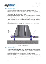
3. Raise the tower until nearly vertical but with tension still on the lift cable (see Figure 12).
Second person can now catch the gin-pole and lower it gently to the ground by applying
downward pressure. DO NOT allow the gin-pole to crash to the ground, this will but serious
strain on the system.
! IMPORTANT:
Continue applying pressure on the gin-pole, till at least
2 tower bolts are fixed.