background image

my!

WIND 

Ltd. 

Soola 1a 


51013 Tartu, Estonia 

Email: info@mywind.ee 

Website: www.mywind.ee 


22 | 

P a g e                                                                                                             2 6 / 0 7 / 2 0 1 9


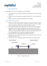
7.  Erection of the turbine 

Step 1: Lifting the tower 

1.  Check that you have performed all previous steps and that all the parts are firmly connected 

together. Check that the gin-pole is connected to the 1

st

 segment. Check that all the shackles 

and  cables  are  firmly  secured  to  the  segments,  gin-pole  and  lifting  equipment.  Clear  all  the 

uninvolved  persons  from  the  area. 

!  IMPORTANT: 

Never  stand  near  or  under  the  tower  or 

gin-pole when raising or lowering the tower. 

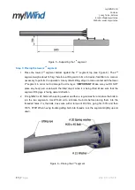
2.  Make sure that the wires are ran through the hole for wires and that during lifting they cannot 

move between the tower 1

st

 segment and the base plate. 

! HINT: 

Fix the wires with the cable ties to one of the M27 threaded bars.  

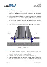
3.  Raise the tower slowly 

– carefully observing the tension in the cables. If your lifting equipment 

does not have enough power or begins to slip, stop the lifting process immediately and gently 

lower the tower back to the ground. DO NOT perform any pumping movement to gain more 

power. 

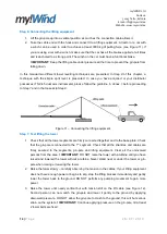
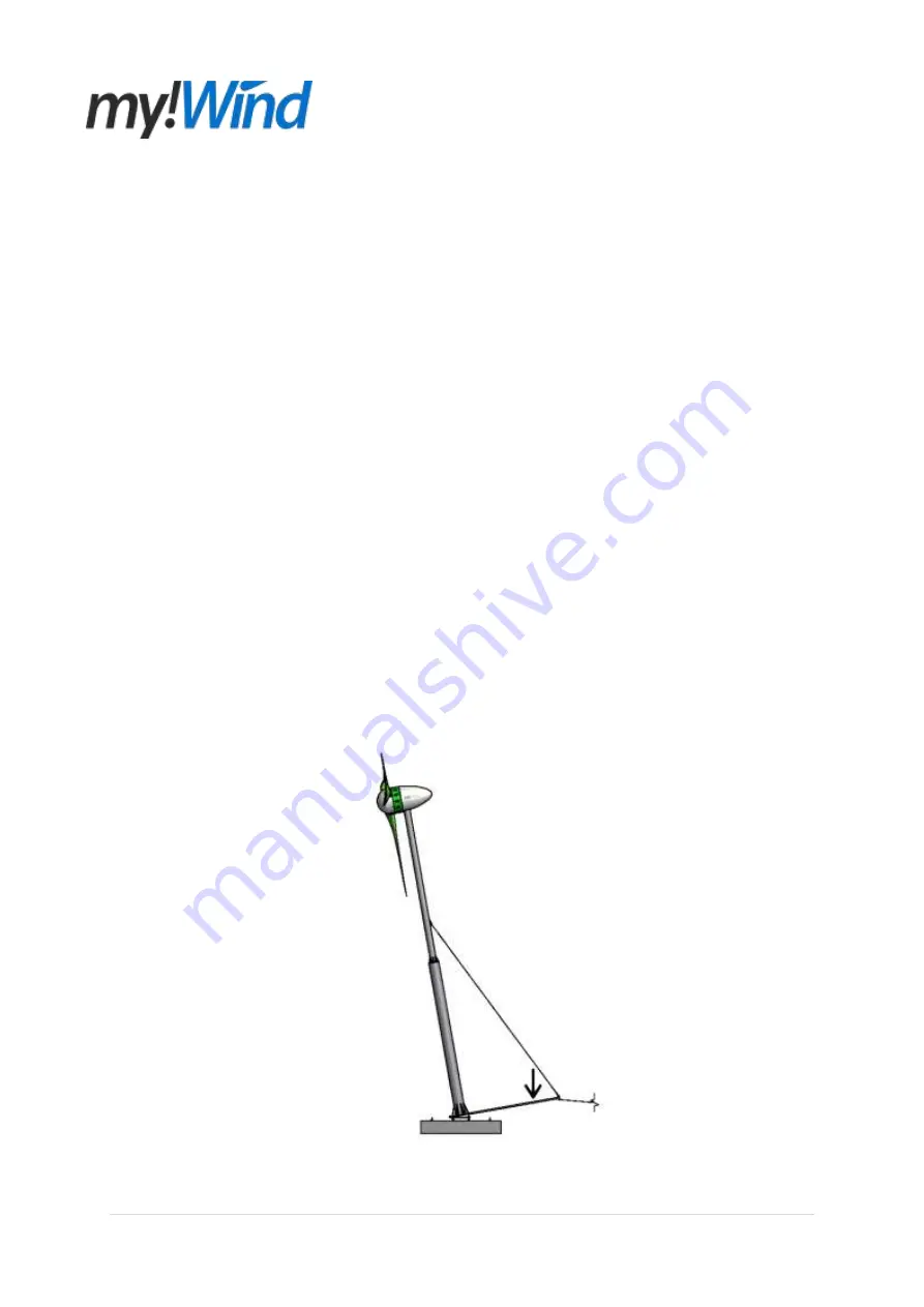
4.  Raise  the  tower  until  nearly  vertical  but  with  tension  still  on  the  lift  cable  (see  Figure  22). 

Second  person  can  now  catch  the  gin-pole  and  lower  it  gently  to  the  ground  by  applying 

downward  pressure.  Do  not  allow  the  gin-pole  to  crash  to  the  ground,  this  will  but  serious 

strain on the system. 
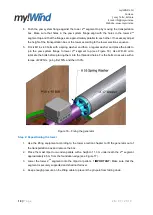
!  IMPORTANT: 

Continue applying pressure on the gin-pole, till at least 

2 tower bolts are fixed. Remember that now more pressure is required, as the system is much 

heavier with the turbine. 


Figure 22 

– Catching the gin-pole 

Summary of Contents for 10 kW wind turbine

Page 1: ...my WIND Ltd Soola 1a 51013 Tartu Estonia Email info mywind ee Website www mywind ee 1 P a g e 2 6 0 7 2 0 1 9 my Wind Ltd 10 kW wind turbine 10m Tower Installation Manual...

Page 2: ...Placing the tower base plate 9 Step 2 Placing the tower 1 st segment 10 Step 3 Placing the tower 2 nd segment 11 Step 4 Placing the gin pole 12 Step 5 Placing the gin pole cables 13 Step 6 Connecting...

Page 3: ...S 2 45 dual axis inclinometer 25 Annex 2 Tower verticality 26 General remarks Please read this manual thoroughly through before beginning the assembly No guarantee is assumed by my WIND for the correc...

Page 4: ...possible use a my Wind distributor who has received a corresponding training to carry out the installation for you 2 Prior to installation 2 1 Important safety instructions 1 Read understand and foll...

Page 5: ...cables and available open area may require the my Wind to be installed in a less then optimum location In general my Wind will produce more power if installed on a taller tower However towers are expe...

Page 6: ...dation for the tower and turbine Depending on the length of the vehicle and the method used to raise the tower over 18 m might be required on the other side of the foundation for the vehicle lifting c...

Page 7: ...5 Zn Cylinder Head Cap Screw 6 DIN 933 M16 x 40 Zn Hex Head Bolt 16 DIN 933 M20 x 45 Zn Hex Head Bolt 2 DIN 975 M27 x 500 Zn Threaded Bar 6 DIN 127 A 8 Zn Spring Washer 20 DIN 125 A 8 4 A2 Washer 48 D...

Page 8: ...d at least 400 kg 1 11 m rod or 12 m strong blank cable For pushing the wires through the tower 1 Fork lifter tractor crane At least 400 kg of lifting force at least 3000 kg of pulling force 1 Truck w...

Page 9: ...ughly 95 mm from the foundation surface Use WD 40 oil to lubricate the nuts before placing them on the bars 2 Place the tower base plate onto the washers and use a spirit level to level the base plate...

Page 10: ...e you DO NOT place any body part underneath the lifted object while it is being lifted 2 Once the tower segment hinge and base plate hinges are coaxial place the M27 x 500 threaded bar through the hin...

Page 11: ...contact with the tower 2 st segment in order not to damage the zinc layer IMPORTANT Make sure you DO NOT place any body part underneath the lifted object while it is being lifted Make sure that the s...

Page 12: ...RTANT Make sure that the segment is securely supported and shall not fall over Figure 7 Supporting the 2 nd segment Step 4 Placing the gin pole 1 Place the gin pole hinge pipes between tower 1 st segm...

Page 13: ...ment lifting eye pos 1 and the gin pole lower lifting eye pos 2 see Figure 9 and 10 2 Take the 6x19 8 mm cable lifting cable with thimble at one end and a hook at the other end and connect the thimble...

Page 14: ...ip Step 8 Figure 11 Connecting the lifting equipment Step 7 Test lifting the tower 1 Check that all the tower segments are firmly connected together and to the base plate Check that the gin pole is co...

Page 15: ...gment to the tower base plate see Figure 13 Use WD 40 oil to lubricate the bolts before placing them into the threaded holes Fix the bolts cross wise with a torque of 434 Nm going first 50 and then 10...

Page 16: ...upper M27 nuts from the threaded bars this could result in the tower falling down 4 Once the tower is vertically levelled fix the M27 nuts cross wise with a torque of 1080 Nm going first 50 and then 1...

Page 17: ...essure on the lifting cable to prevent the gin pole from falling down 6 Assembling the turbine Step 1 Placing the generator 1 Remove lid and yaw system flange side of the generator transportation box...

Page 18: ...tem flange to tower 2 nd segment top see Figure 16 Use WD 40 oil to lubricate the bolts before placing them into the threaded holes Fix the bolts cross wise with a torque of 222 Nm going first 50 and...

Page 19: ...lts with a spring washer and then a regular A2 washer and place the bolts to join the three blade cover holders to the blade holder back flange see Figure 18 Use WD 40 oil to lubricate the bolts befor...

Page 20: ...53 Nm going first 50 and then 100 TIP Fix at first two bolts with a small torque and then place to others This will make the bolt placement easier 3 Once the blade is fixed place a support under the b...

Page 21: ...cover and place it on top and inside of the cooling ring in a way that the tower passes through the hole for tower see Figure 21 Align the eight fixing holes in the cover and in the cooling ring 2 Ta...

Page 22: ...1 st segment and the base plate HINT Fix the wires with the cable ties to one of the M27 threaded bars 3 Raise the tower slowly carefully observing the tension in the cables If your lifting equipment...

Page 23: ...d bar connecting the gin pole to the tower 1 st segment and remove the gin pole see Figure 8 4 Place the A 28 washers and M27 nuts back onto the M27 threaded bar to be used again for the gin pole if n...

Page 24: ...nd turbine We appreciate your support of our company and products Follow the Electrical connection manual on how to connect the turbine to the controller and after that you are ready to begin harnessi...

Page 25: ...luence of side pressure 5 Take the dual axis inclinometer display and take the reading from the device If the X and Y axis readings on the display are more than 0 5 from the 0 perform next steps of th...

Page 26: ...te from which the turbine is self orienting In this case the turbine blade cover is pointing at the direction which needs to be lifted Use the technique described in Chapter 5 Step 8 to level the towe...

Reviews:

Related manuals for 10 kW wind turbine