background image

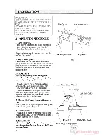
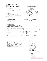
Table Fix Bolt

Table Fix Bolt

Back Table

Backgauge
Screw

Screw

Backgauge
Handle Shaft

Hand Wheel

(B)

(B)

(C)

Position the back 
table so that the 
tip of this screw 
hits against the 
casting frame.

- Side Guide (C) on front table should be aligned 

with side guide (B) on back table. 

Fig. 7-1

Summary of Contents for Standard PC II-

Page 1: ...Instruction Manual Provided By http www MyBinding com http www MyBindingBlog com Standard PC 64 II Paper Cutter...

Page 2: ......

Page 3: ...ng from improper or inadequate maintenance by customer unauthorized modification or misuse operation outside of the environmental specifications for the product Horizon International Inc pursues a pol...

Page 4: ......

Page 5: ......

Page 6: ...2...

Page 7: ...3 Knife Lamp Left Small Cover...

Page 8: ......

Page 9: ...Fig 2 4 counterclockwise until paper lift is released Remove lift of paper 7 Job complete Turn key switch off and remove key Fig 2 4 Unplug power cord IMPORTANT Keep key switch at safe place by an aut...

Page 10: ......

Page 11: ...7 Cut Button A...

Page 12: ......

Page 13: ...Cycle knife by depressing cut buttons A and B separately with the interval of 0 5 seconds or more to return the knife to the home position Fig 4 5 2 Turn on power 9...

Page 14: ......

Page 15: ......

Page 16: ...12 Cut Button A...

Page 17: ......

Page 18: ......

Page 19: ...left 15...

Page 20: ...ble Backgauge Screw Screw Backgauge Handle Shaft Hand Wheel B B C Position the back table so that the tip of this screw hits against the casting frame Side Guide C on front table should be aligned wit...

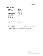
Page 21: ...op Machine Weight Other Features 120V 60Hz 14A 220V 50Hz 5 6A 220V 60Hz 6 8A 240V 50Hz 5 9A 1 1kw Max 990 mm W 38 9 1120 mm D 44 1 1280 mm H 50 4 900 mm 35 4 290 kg 638 lb Back Gauge Dial at Front Tab...

Page 22: ......
Reviews: