Chapter 5 Maintenance and Inspection
UD-series Screw Compressor
5.5 Reassembly
5-70
Disassembly
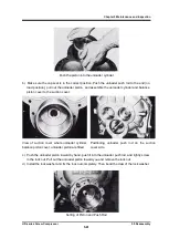
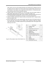
a) Remove the Phillips screw (part number 140) that fixes the indicator pointer (part number
139) to the shaft.
b) Remove the Phillips screw (part number 138) that fixes the dial plate (part number 137) to the
dial plate support.
c) A potentiometer mounting plate (part number 130) is installed between the dial support [1]
(part number 134) and the dial support [2] (part number 135).
Fix the dial support [1] and
loosen it by turning the dial support [2] counterclockwise to remove the support [2].
d) Remove the two right and left supports and remove the potentiometer (part number 129)
while it is attached to the mounting plate.
e) The potentiometer is attached to the mounting plate with three Phillips screws.
f)
The micro-switch (part number 125) is fixed with two long Phillips screws (part number 126).
The micro switch can be removed by loosening these screws.
g) The right side of the micro-switch is for the no load (0 %) position signal, and the left side is
for the full load (100 %) position signal.
On the left side, the cam on the outside of the
actuating cam is used, and a micro switch setting plate (part number 123) under the micro
switch is fixed to the micro switch base plate with a Phillips screw (part number 124).
h) Other parts can also be removed by removing the tightening screws.
Inspection
a) Mainly check the operation of the contacts of electrical parts.
Since the potentiometer is a full
rotation type, check that the resistance value changes smoothly throughout the full revolution.
If the surrounding environment is bad (in a corrosive gas atmosphere, in a place with a lot of
water, or in a place with strong vibration), the internal resistance wire may be defective due to
corrosion or wear. So it needs to be inspected.
b) Check the operation of the microswitch contacts using a tester.
Also check the rotation of the
microswitch roller.
c) Inspect the cam for contact wear and damage.
Reassembly / Adjustment
The procedure is completely reverse to the disassembly, but adjustment after assembly is
important.
These adjustments are made after the microswitch base plate is attached to the
unloader cover.
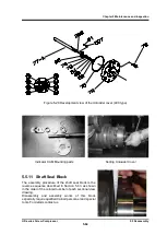
a)
Since the unloader cover was assembled with the unloader slide valve position (unloader
piston) in the unloaded position, the unloader indicator cam is in the unloaded position.
Therefore, use the hexagon socket set screw (part number 128) of the micro-switch cam to
fix it to the set hole on the shaft of the unloader indicator cam.
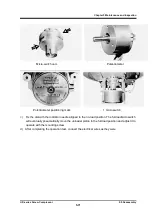
Since the position is unloaded
as described above, align the operation rod (roller) of the micro switch with the recess of the
(inner) cam on the unloader cover side of the micro switch cam (see arrow
) to fix the
micro switch.
b)
To assemble the potentiometer, a spring pin is inserted into a part of the shaft of the
potentiometer.
Align that pin with the key groove (cut-out part) of the micro switch cam and fix
it with the dial plate support [2] (part number 135).

