Chapter 2
Compressor Specifications and Structure
UD-series Screw Compressor 2.4
Compressor Structure and Mechanism
2-14
Why the Vi Needs to Be Chosen?
[1] You ca set the Vi that is suitable for use refrigerant.
Internal volume ratio Vi is expressed as follows with the compression ratio.
Pd: discharge pressure, Ps: suction pressure,
κ
: ratio of specific heats (a constant specific to each refrigerant).
As seen from the formula, the Vi corresponding to a certain pressure ratio varies with the type of
refrigerant gas.
[2] You can operate the compressor most efficiently under varying conditions.
Compressors of the same model will be used for a variety of applications whose load conditions are
different, e.g. air conditioning, cold storage, and freezing. The compressor, however, can be
operated most efficiently when the Vi is matched with the load condition.
For example, if a conventional M port compressor with the fixed Vi is used for a low compression
ratio application (an application with small difference between suction and discharge pressures), a
pressure higher than the necessary pressure will be reached before the discharge port opens as
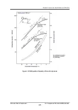
shown in the lower right graph of Figure 2-13 in next page. This means that power will be used
wastefully for unneeded compression.
Conversely, if the same compressor is used for a high compression-ratio application (an application
with large difference between suction and discharge pressures), the discharge port will open before
the refrigerant gas pressure has risen to the necessary level. This would cause the refrigerant gas
in the outlet piping to flow back through the discharge port as shown in the lower left graph of Figure
2-13 unless the flowing-back gas is overcome by driving the compressor using extra power.
In summary, the greatest benefit provided by properly setting the Vi value is that the rotor driving power
(brake horse power) is made optimum for the load. The refrigeration capacity generally changes little
even if the Vi is varied. However, the efficiency of the brake horse power becomes the maximum and
the loss of power is minimized if the Vi is optimally adjusted.
The performance curves in below Figure 2-12 show the relationship between the refrigeration capacity
and the brake horse power. The curves indicated by thick solid lines in the graph represent the brake
horse powers most efficient for achieving the specific refrigerating capacities.

