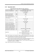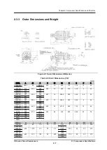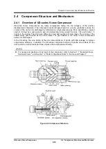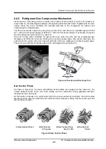
Chapter 2
Compressor Specifications and Structure
UD-series Screw Compressor 2.4
Compressor Structure and Mechanism
2-17
2.4.4 Bearings and Balance Piston
The M rotor and F rotor are supported at their both ends by the side bearings in the suction cover and
the main bearings in the bearing head. These bearings use sleeve type white metal lined bearings.
In addition, the thrust bearings located outside the main bearings support the thrust loads working on
the rotors, which result from both the rotation of the rotors and the difference in refrigerant gas pressure
that takes place during the compression process. For the thrust bearing, UD-series compressors use
the angular contact ball bearing.
In particular, because the M rotor is a kind of helical gear and also because the thrust force produced
by discharge pressure is larger than that for F rotor. To reduce the load acting on the thrust bearing of
the male rotor, a hydraulic piston (balance piston is provided in the suction cover.
2.4.5 Shaft Seal
To prevent refrigerant gas leakage, a reliable mechanical seal assembly is used for the shaft seal of the
male rotor, which is the compressor
’
s drive shaft.
Mechanical seal assembly is mainly composed of "rotating ring" installed on the rotor shaft and
"stationary ring" installed in the seal cover. Rotating ring rotates with the shaft, and slides each other
with the stationary ring while maintaining a micron class gap. The sliding each other place is called as
the sliding surface.
For example, the Balance Bellow Single Seal which is currently used as standard seal, employs a
stationary ring (mating ring) made of special cast steel, a rotating ring made from carbon, and O-rings
for the packing.
2.4.6 Capacity Control
The unloader slide valve, which is activated hydraulically via the unloader cylinder and the unloader
piston, automatically carries out capacity control (suction gas amount control) of each UD-series
compressor.
The unloader indicator assembly is connected to the unloader cylinder via the indicator cam, allowing
the indicator to indicate the positions of the unloader slide valve. The indicator cam has a spiral groove,
in which the guide pin implanted in the unloader slide valve push rod is movably inserted. As this pin
and cam combination converts a linear displacement of the unloader slide valve into an angular
displacement, the pointer of the indicator indicates the position of the slide valve.
In addition to the visual reading of the position of the unloader slide valve, the unloader indicator
assembly can also provide the following electric signals for output to external devices: ON/OFF signals
produced by the cam mechanism contacts and resistance signals produced by a potentiometer.
Mechanisms
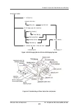
2.4.7 Oil Supply Route
Depending on applications, the UD-series compressors use either of the following types of oil supply
system.
•
Forced oil supply system:
This system uses pump-pressurized oil for both the lubrication and capacity control purposes.
•
Differential pressure oil supply system:
This system supplies lubrication oil under the effect of the differential pressure, but uses pump
pressurized oil as the capacity control oil and as the lubrication oil during startup of the compressor.


