Chapter 5 Maintenance and Inspection
UD-series Screw Compressor
5.4 Disassembly and Inspection
5-25
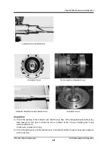
Inspection
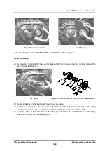
Make sure that the positioning pin is not bent (it might bend when removing the cover).
5.4.7 Thrust Bearings
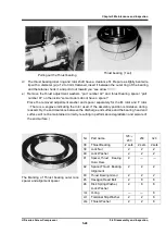
Thrust bearings “part number 38” are an important component in the performance of screw
compressors.
Improper installation of this part may cause malfunction.
Pay attention to disassembly and
assembly, and work carefully.
This thrust bearing is a face-to-face combination angular contact ball bearing and uses a special
retainer.
The outer ring is a clearance fit with the bearing head and is designed to receive only thrust
load.
Not only does this bearing support the thrust load, it also serves to maintain precise the end
clearance between the rotor end face and the bearing head discharge end face.
Disassembly
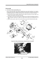
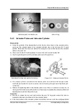
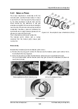
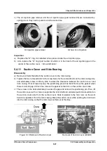
a) Among the bolts "Part No. 18-1 and 18-2"
tightening the bearing cover, replace the two
bolts at the upper position without head
"safety bolts" and remove all other bolts.
b
)
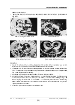
There are two screw holes for the service
holes at the 2 o'clock and 8 o'clock positions
on the bearing cover. "A vinyl cap is attached
at the time of shipment."
。
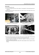
After placing a
container for receiving oil under the bearing
cover, attach two removed bolts to the screw
holes and screw them in alternately to widen
the gap with the bearing head on average.
When there is a gap, the oil inside will flow
out.
c
)
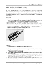
If the gap is further widened, the cover will
come off from the positioning pin near the
service hole.For 200, 250 and 320 models,
eye bolt screws are machined on the upper
side of the flange on the bearing cover.
The
product is heavy. Hang it with a lifting slings
to remove it.
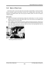
Safety Bolt
Removing bearing cover bolt


