Chapter 5 Maintenance and Inspection
UD-series Screw Compressor
5.4 Disassembly and Inspection
5-35
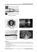
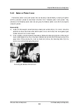
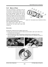
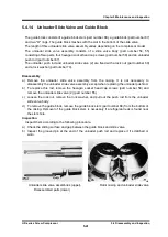
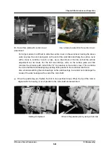
Balance piston sleeve locking
spring pin(320
,
400Type)
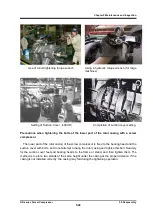
Removing the Retaining ring for the balance
piston sleeve
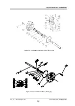
d) The balance piston sleeve (part number 33) has a cutout and is fixed by matching two
hexagon socket set screws to the screw holes on the suction cover side.
Pull out the M side
or loosen the F side and let the head part of the M side into it.
e) Remove the stop ring of the balance piston sleeve with Type 2 as it is.
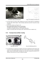
f) Remove the balance piston sleeve.
The sleeve is a clearance fit so it can be pulled out easily.
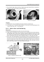
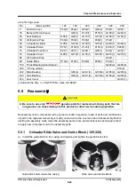
g) Remove the "O" ring (part number 35) and the "O" ring spacer inside the sleeve.
h) If you plan to remove the side bearings, also remove the stop ring (part number 37) inside.
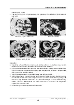
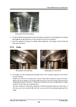
Inspection for Balance Piston and Balance Piston Sleeve
There is a mark of wear on the inner surface of the balance piston sleeve, but this is normal
because the clearance between the balance piston and piston sleeve is smaller than the clearance
between the rotor shaft and bearing.
A large gap is provided on the outer circumference of the balance piston sleeve to prevent the
bearing load from being applied to the balance piston, so further wear does not progress.
However, if the side bearings are severely worn, the balancing piston will also be worn. Check
carefully.
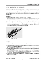
Be sure to replace the "O" ring.
The "O" ring serves to match the gap with the outer
circumference of the balance piston sleeve with the core of the balance piston due to its elasticity.

