Chapter 5 Maintenance and Inspection
UD-series Screw Compressor
5.4 Disassembly and Inspection
5-40
5.4.13 Bearing Head and Main Bearing
On the side where the rotor of the bearing head (part number 11) is installed, a gas discharge port
that is determined by the operating conditions of the compressor is machined.
This discharge port
affects the performance of the compressor.
The bearing head also has a bearing that supports the
discharge side of the rotor.
There is a difference in the shape of the discharge part between UD
type and G type.
Disassembly
a
)
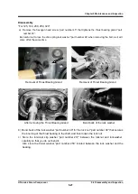
Bearing heads and rotor casings do not normally need to be separated.
Pull out all the hexagon socket head cap screws (part number 2) that tighten the casing and
bearing head, and drive the parallel pin (part number 3) into the rotor casing side.
b) Screw the bolt (part number 2) into the screw hole on the casing side and push it in.
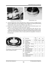
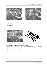
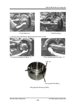
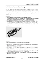
c) The main bearing can be removed by pulling out the stop ring (part number 29) from the bearing
cover side of the bearing head with the stop ring pliers and pressing the main bearing. If the fitting
is hard, do not hit the bearing directly, but use a copper, aluminum or plastic wire. Replace the "O"
ring (part number 432) on the outer circumference of the bearing.
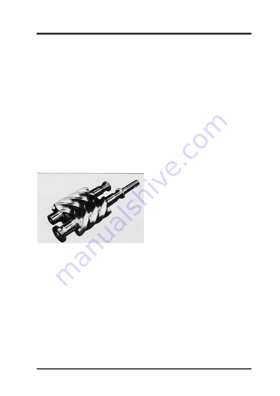
M rotor and F rotor
Inspection
You should always inspect them according to the following procedure.
a) Visually inspect the bearing surface of the main bearing (part number 27) fixed to the bearing
head to ensure that there is no abnormality.
If it is abnormal, replace it with a new one.
b)
Visually inspect the bearing surface of the discharge port on the rotor side to make sure there
are no abnormalities.
If it is severely damaged, the end clearance adjustment may not be correct.
Garbage
contained in the gas may cause scratchesVisually inspect the contact surface between the
casing and the slide valve to make sure there are no abnormalities..
c)
Visually inspect the contact surface between the casing and the slide valve to make sure
there are no abnormalities.


