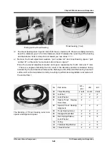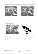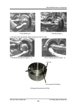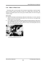
Chapter 5 Maintenance and Inspection
UD-series Screw Compressor
5.5 Reassembly
5-42
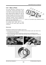
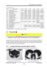
List of O-rings used
No.
Install position
125
160
200
250
320
400
9
Suction Cover
P42(2) P42(2)
G55(2)
G60(2)
P58(1)
G95(1)
35
Balance Piston Sleeve
-
G95(1)
P120(1)
P150(1) G190(1) G240(1)
49
Seal Retainer
G85(1) G90(1)
G115(1)
G135(1) G160(1) G160(1)
59
Oil Injection Pipe
P30(2) P30(2)
P40(2)
P46(2)
P32(1)
-
63
Unloader Cylinder
G95(1) G125(1) G150(1)
G190(1) G240(1) G300(1)
65
Unloader Piston
P75(1) P100(1) P125(1)
P155(1) P200(1) P265(1)
73
Unloader Push Rod
P21(1) P21(1)
G30(1)
G35(1)
P44(1)
G45(1)
75
Unloader Cover
G85(1) G110(1) G135(1)
G170(1) G210(1) G270(1)
86
Oil Injection Pipe
G30(1)
-
89
Guide Block
P12(2) P16(2)
P20(2)
P20(2)
P24(2)
-
150
Thrust Bearing Gland Spacer
G220(2) G290(2)
325
"O" ring retainer
P70(2)
432
Main Bearing
G85(4)
G22
☆
(4)
G135(4) G165(4) G200(4)
433
Side Bearing
G85(4)
G22
☆
(4)
G135(4) G165(4) G200(4)
674
Seal Cover
G39
☆
(1)
() indicates the Q'ty.
☆
: JIS W1516 No mark: JIS B2401
5.5
Reassembl
y
Be sure to use only
genuine parts for replacement. Using parts that are
not genuine can cause damage to this product or other devices during operation.
Reassembly of the compressor will be carried out after inspection, repair of parts and confirmation
of parts to be replaced.
Assembly is mostly carried out in the reverse order of disassembly.
Before
starting the assembly work, clean the assembly parts, tools, and workbenches and prepare them
to apply new compressor oil to the assembly parts.
5.5.1
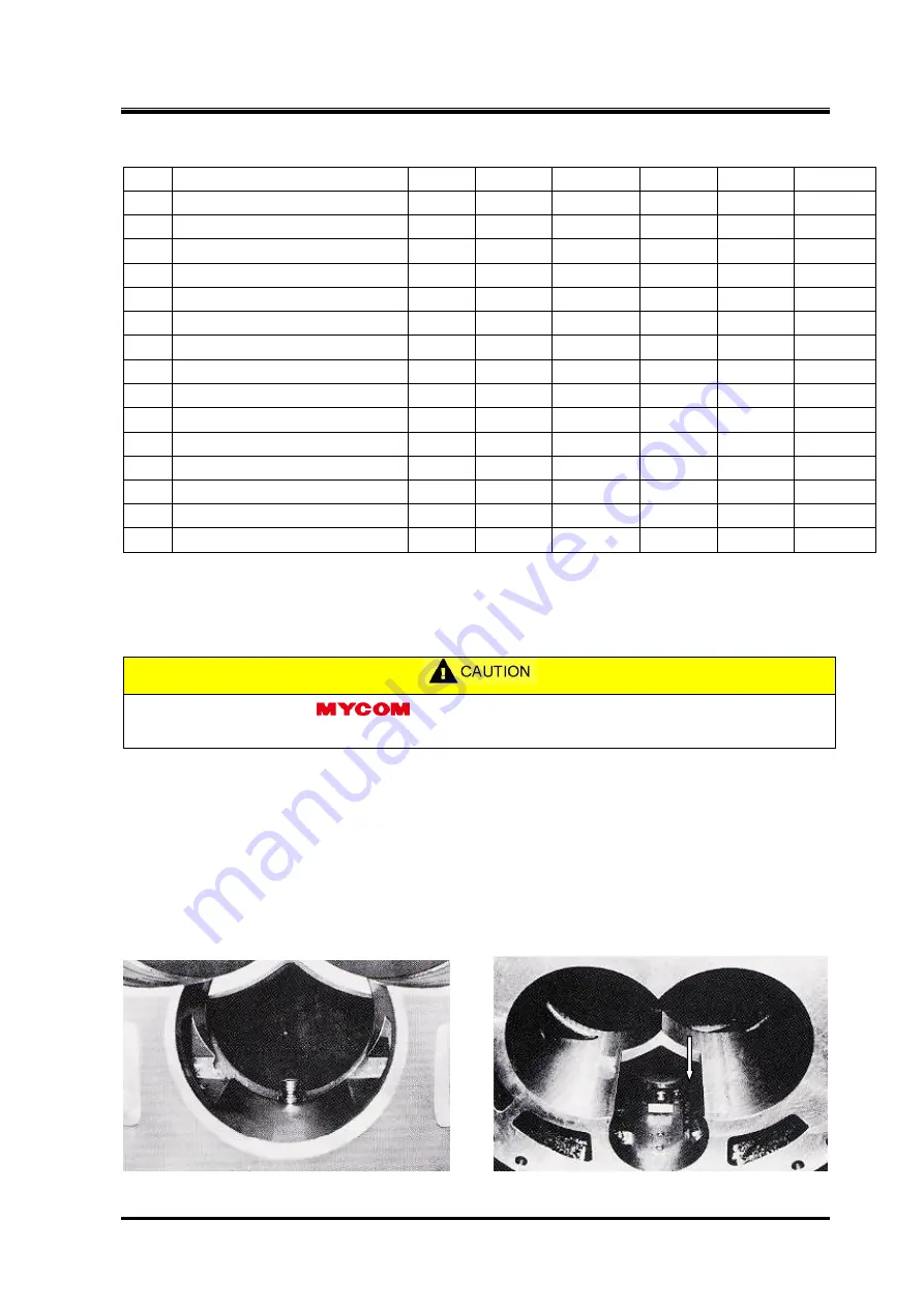
Unloader Slide Valve and Guide Block (125-320)
a)
Install the guide block in the casing and replace and tighten the guide block stem.
Guide block stem inside the casing
Slide Valve and Guide Block

