2202L5JE-DA-C5-N_2015.05.
5 Maintenance and Inspection
Compound 2-stage Screw Compressor
5.5
Reassembly
1612LSC Speed Increaser Type
5-65
5.5.12
Unloader Cover
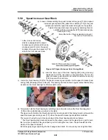
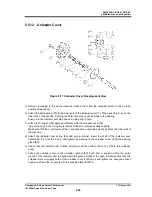
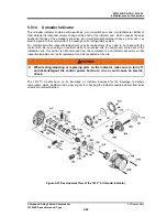
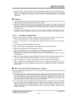
Figure 5-17 Unloader Cover Development View
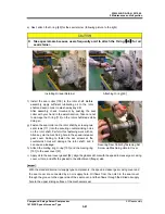
a) Before proceeding to the next procedure, make sure to pull the unloader piston to the no-load
position (toward you).
b) Attach the ball bearing [78] to the axial part of the indicator cam [77]. When pushing in, push the
inner race of the bearing. Pushing the outer race may cause damage to the bearing.
Push up to the indicator cam step and use a stop ring to hold.
c) Attach the V-ring set [82] applying sufficient oil to the unloader cover [74].
One of the rings in the V-ring set is made of rubber to improve sealing capacity.
Make sure that the V protrusion of the V-ring faces the outer side and the lip faces the inner side of
the machine.
d) Attach the indicator cam spring [83] and spring retainer, insert the shaft of the indicator cam
assembled in b) into the V-ring, and tighten the bearing to the unloader cover using the bearing
gland [80].
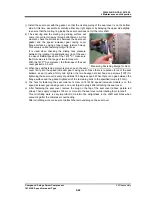
e) Check that the indicator cam rotates smoothly, and then attach the O-ring [75] to the unloader
cover.
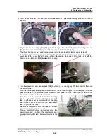
f) Attach the unloader cover to the unloader cylinder [60]. Push from a position where the spiral
groove of the indicator cam is aligned with the guide pin [68] of the push rod. Make sure that the
unloader work oil supply hole of the unloader cover is facing up and tighten the hexagon socket
head cap screws [76] to secure it at the specified torque 10N
・
m.

