2202L5JE-DA-C5-N_2015.05.
5 Maintenance and Inspection
Compound 2-stage Screw Compressor
5.5
Reassembly
1612LSC Speed Increaser Type
5-66
5.5.13
Shaft Seal Block
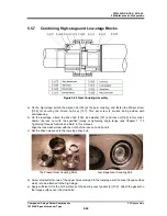
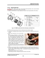
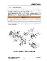
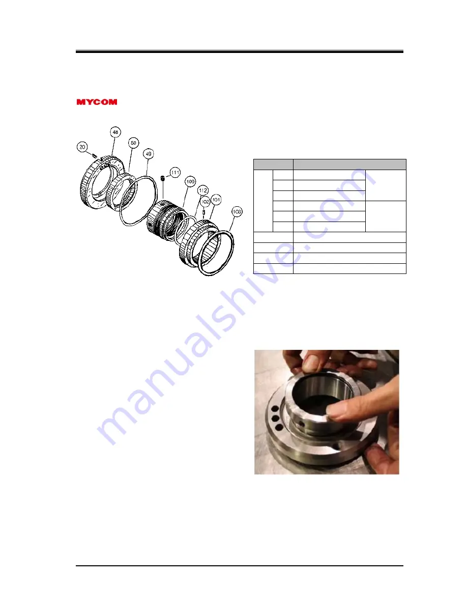
The BBSE (balance bellows single) type of the mechanical seal assemblies used in current standard
screw compressors as standard specification.
In addition, the BOS (balance O-rings single) type may be used by the specification of the customer.
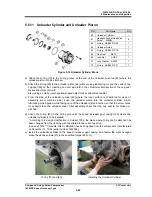
Figure 5-18 BBSE Type Mechanical Seal Assembly and Related Parts
a) Before assembly, clean the part of the rotor shaft where the seal will be installed.
b) In particular, immediately before assembly, recheck the step part for mounting the shaft seal for
damage.
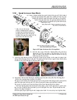
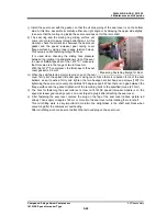
c) Attach the oil seal [50] to the oil seal retainer
[48].
Since the design modification in November 2002,
the oil seal attachment direction has changed from
the oil seal lip facing the atmosphere side to it
facing the opposite side. This was in order to
improve oil flow from inside the seal box and
ensure that pressure is not excessive. Using a
resinous material such as Teflon as a pad, gently
hit the oil seal while pushing it evenly and fully to
assemble. When it has been pushed in fully, the
sound and feedback will change.
After assembly, check that the seal is aligned with
the retainer and that they are even from the other
side.
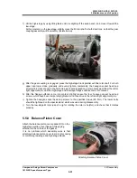
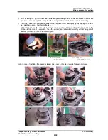
d) Install the oil seal retainer with the oil seal attached along the rotor shaft using two M8 eyebolts. At
this time, ensure that the retainer’s oil hole is on the upper side of the rotor shaft, and accurately
align the spring pin [20] for stopping rotation on the speed increaser gear casing cover with the
retainer notch part.
After assembly, rotate the retainer’s eyebolts to
check that they are secure. If they are secure, the retainer will not rotate.
P/N
Part Name
100
101
Mating ring
Stationary
ring
102
Insert lock pin
103
O-ring
109
Seal collar
Rotating
ring
111
Seal collar set screw
112
O-ring
20 Spring
pin
48
Oil seal retainer
49 O-ring
50 Oil
seal

