2202L5JE-DA-C5-N_2015.05.
5 Maintenance and Inspection
Compound 2-stage Screw Compressor
5.5
Reassembly
1612LSC Speed Increaser Type
5-70
5.5.14.1
Potentiometer
The potentiometer of the 1612**C indicator is of the full rotation type. It senses the continuously
variable position (indicated load of 0 % to 100 %) of the unloader slide valve, and feeds the sensed
position as electric signals to the control side of the package unit or refrigerating system. Life
expectancy of the potentiometer varies significantly depending on the compressor's installation
environment (with corrosive gas atmosphere or much moisture) or operating state (frequently operated
with partial load, frequently started/stopped, subject to much vibration, etc.). It is a consumable part,
and needs to be replaced periodically depending on the situation.
Disassembly
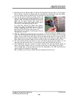
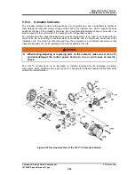
a) Remove the hexagon head cap screws securing indicator glass
【
141
】
, indicator glass gland
【
206
】
and indicator glass support
【
205
】
. At this time, do not mistakenly loosen the phillips screws
【
210
】
on the same surface.
It become possible to remove the indicator shaft assembly with
【
141
】
,
【
202
~
207
】
,
【
210
】,
and
【
211
】
.
b) When remove two hexagon head cap screws
【
147A
】【
147B
】
for each which are securing the
indicator cover
【
146
】
, it becomes possible to remove the indicator cover.
c) Remove the electric wiring of the potentiometer. To avoid future assembly errors, put markings to
indicate positional relationship of wiring by using different colors of tape or the like, and take a note.
d) Remove the phillips screws
【
131
】
of the potentiometer set-plate
【
130
】
. This allows the
potentiometer set-plate with the potentiometer [129] attached to be removed.
The potentiometer shaft is removed with the micro-switch cam [127] and bevel gear [202] attached.
e) The micro-switch cam moves freely in the direction of the shaft can be easily removed because
only the rotation direction is secured by a spring pin [213] in the potentiometer shaft and a notch.
f) The bevel gear [202] is secured to the potentiometer shaft by the set screw [128].
Loosen the set screw, and then pull out the potentiometer spring pin using pliers to remove.
g) Loosening two phillips screws [138] allows the potentiometer and potentiometer set-plate to be
separated.
Inspection
a) On the terminal block, check whether or not the lead wires of the potentiometer are loose.
b) Check for defects such as cracks in the welded portion of the potentiometer lead wires.
c) Rotate the shaft of the potentiometer with hand, and check with a tester whether the resistance
value changes smoothly.
5.5.14.2
Micro-switch
The unloader indicator has two micro-switches and one micro-switch cam, for sensing that the unloader
slide valve is at the 0 % position or the 100 % position of capacity control (indicated load).
If, for any reason, their assembly gets loose or the micro-switch(es) gets faulty, proper sensing will be
disabled, which will cause trouble in operation control of the compressor.
Disassembly
a) Same work as disassembly procedure of the potentiometer a) to d).
b) Remove the electric wiring of the micro-switch. To avoid future assembly errors, put markings to
indicate positional relationship of wiring by using different colors of tape or the like, and take a note.

