2202L5JE-DA-C5-N_2015.05.
2 Compressor Specifications and Structure
Compound 2-stage Screw Compressor
2.3 Compressor Specifications
1612LSC Speed Increaser Type
2-2
2.3 Compressor
Specifications
2.3.1 Standard
Specifications
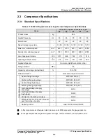
Table 2-1 1612LSC Speed Increaser Type Screw Compressor Specifications
I t e m
1 6 1 2 L S C S p e e d I n c r e a s e r t y p e
5 2
6 2
5 3
6 3
5 4
Product mass
kg
560
Applied frequency
Hz
50
60
50
60
50
Motor Poles
-
4P
4P
2P
2P
2P
Speed increaser gear ratio
-
1.809
1.809
1.220
1.220
1.472
Male rotor rotational speed
min
-1
2610 3150 3610 4350 4350
Female rotor rotational speed
min
-1
1740 2100 2407 2900 2900
Low-stage swept volume
m
3
/h
551 665 762 918 918
High-stage swept volume m
3
/h
174 210 241 290 290
Applied refrigerant
-
Ammonia, Hydrofluorocarbon, other
Design pressure
MPa
2.6
Capacity control range (Actual load)
%
10 to 100
Rotation direction
-
Crockwise viewed from motor
Con
ne
ction pi
pe si
ze
Suction flange low-stage
-
MYCOM 125A (5
″
)
Discharge flange low-stage
-
MYCOM 80A (3
″
)
Suction flange high-stage
-
MYCOM 80A (3
″
)
Discharge flange high-stage
-
MYCOM 65A (2½
″
)
Journal lubricating oil supply
(low-stage)
- Rc1/2
Journal lubricating oil supply
(high-stage)
- Rc3/8
Oil injection lubricating oil supply
- Rc3/8
Mechanical seal and speed increaser
gear lubricating oil supply
- Rc1/4
Capacity control
-
Load: Rc1/4, Unload: Rc3/8
In this manual unless otherwise noted, pressure units MPa represents the gauge pressure.
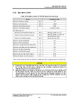
For usage temperature ranges and pressure ranges, refer to Section2.3.2 “Operation Limits”.

