2202L5JE-DA-C5-N_2015.05.
5 Maintenance and Inspection
Compound 2-stage Screw Compressor
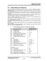
5.4 Disassembly and Inspection
1612LSC Speed Increaser Type
5-23
5.4.6
Speed Increaser Gear Casing
Block
The speed increaser gear casing block needs be
disassembled when inspecting the thrust bearing
block on the low-stage, pulling out the rotors, or
inspecting the speed increaser gears.
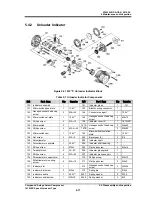
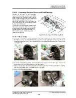
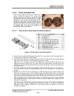
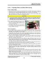
For replacing the thrust bearing [189],
pilling out the speed gear increaser
gear spindle [188] is required.
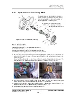
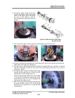
Figure 5-5 Speed Increaser Gear Casing
5.4.6.1 Disassembly
It is possible to separate the speed increaser gear block
as an entire assembly.
However, remove the side bearing for the speed increaser gear
spindle before separating the speed increaser gear casing assembly.
a)
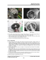
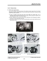
Remove the speed increaser drive gear side bearing [183]. The side bearing is positioned by the
spring pin [184] inside the speed increaser gear casing and held by the speed increaser gear
casing cover [171].
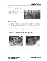
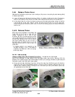
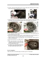
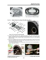
Screw two M8 eyebolts into threaded holes on the side bearing, hang a pipe on the eyes of the
eyebolts and pull out by tapping the pipe lightly toward you (following picture to the left).
b)
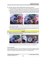
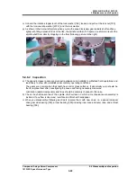
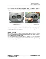
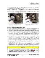
Screw M12 eyebolts into two threaded holes on the upper surface of the speed increaser gear
casing, and hook lifting tools onto the eyebolts (above picture to the right).
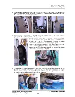
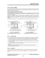
c) Remove all the hexagon socket head cap screws [18-1]. The casing is held in position by the
alignment pins [19-1], so it remains attached to the bearing head [11-1].
d)
Tap the alignment pins [19-1] toward the bearing head [11-1].

