2202L5JE-DA-C5-N_2015.05.
5 Maintenance and Inspection
Compound 2-stage Screw Compressor
5.4 Disassembly and Inspection
1612LSC Speed Increaser Type
5-25
h)
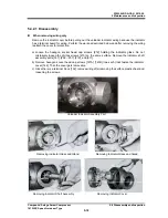
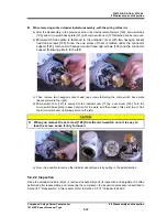
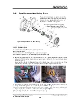
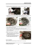
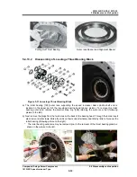
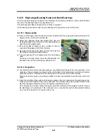
Unbend the rotation stopper tooth of the
lock washer [270] for the lock nut [269] as
shown in the picture below, then loosen
the lock nut and remove it with the
torsional slip washer [237-D] and the lock
washer.
i)
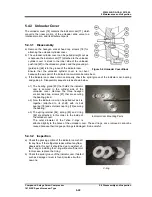
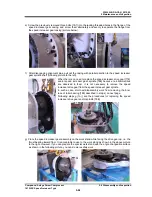
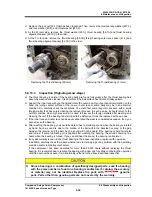
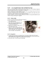
Then remove the speed increaser gear spacer [176] (following picture to the left).
j)
Screw two eyebolts into threaded holes on the drive gear [174] as sown in the above picture to the
right to remove the drive gear with lifting it.
k)
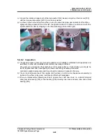
The inner race of roller bearing [185] which supports the spindle shaft end is attached on the shaft
end with shrink-fitting. Pull out the inner race of the roller bearing while heat up it by using a
blowtorch or the like.
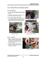
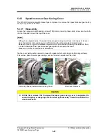
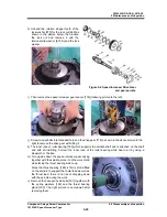
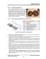
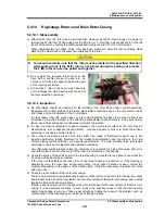
m) Turn upside down the speed increaser gear casing
together with the spindle, place it on the work stand
while facing the thrust bearing side to up.
Since the thrust bearing [189] is firmly shrink-fitted
on the spindle to support the radial load as well as
the thrust load, there is no risk of dropping down
with the spindle during the work.
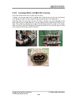
n)
Remove the hexagon head bolts [191] together with
the spring washers [192] and the thrust bearing
gland [190]. The right picture is overviewed after
removing them.
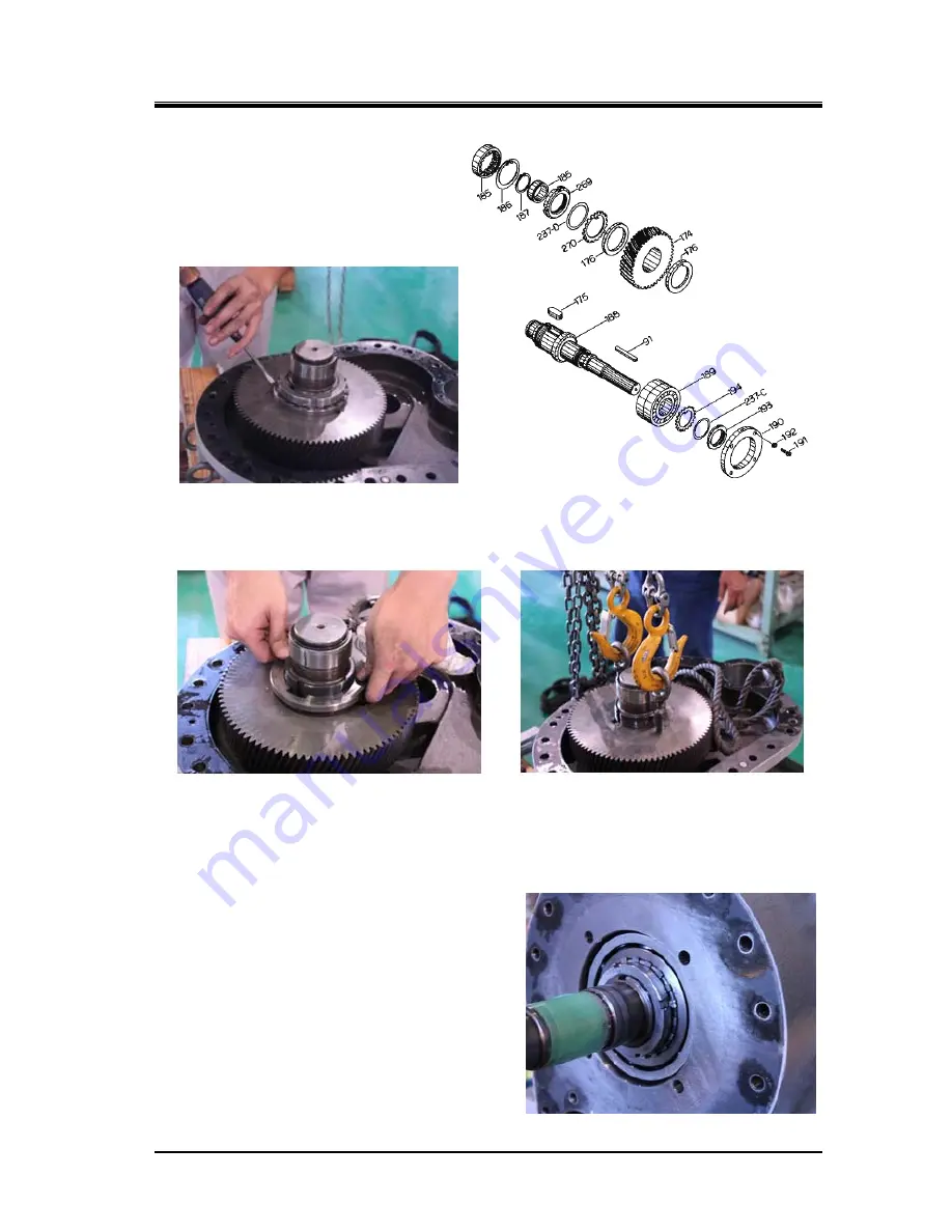
Figure 5-6 Speed Increaser Drive Gear
and gear spindle

