2202L5JE-DA-C5-N_2015.05.
5 Maintenance and Inspection
Compound 2-stage Screw Compressor
5.4 Disassembly and Inspection
1612LSC Speed Increaser Type
5-26
o)
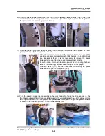
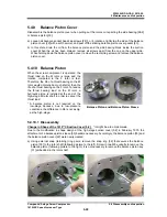
Unbend the rotation stopper tooth of the lock washer [194], loosen and pull out the lock nut [193]
with the torsional slip washer [237-C] and the lock washer.
p)
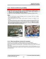
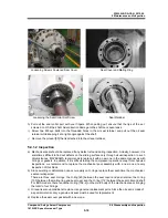
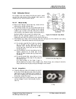
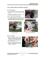
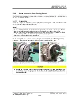
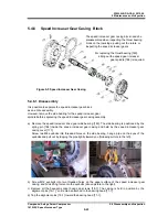
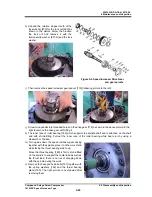
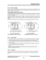
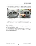
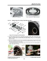
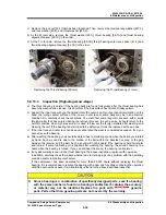
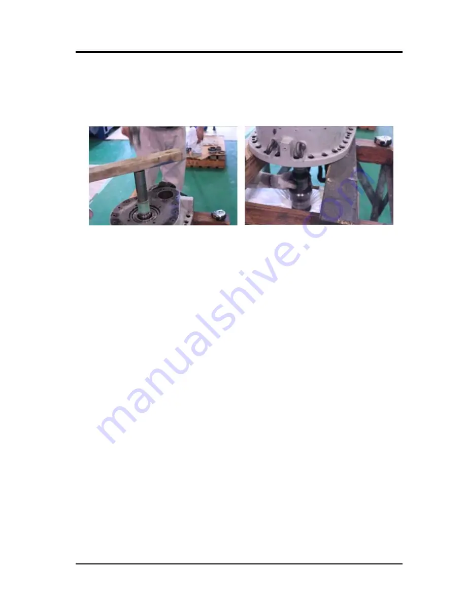
As shown in the below left picture, when you tap the speed increaser gear spindle shaft end face
lightly with fitting a plastic block or the like, the spindle will fall off. Prepare a cushion to prevent the
spindle shaft from directly dropping on the floor (following picture to the right).
5.4.6.2 Inspection
a)
The speed increaser gears are given extra allowance in durability to withstand hard operations and
least likely to show abnormalities under ordinary operating conditions.
The gears are normal when their teeth have mirror gloss surfaces. If abnormally worn should be
found, replace them after investigating the cause and taking necessary measures.
Lubrication-related components and lines should be primarily checked in this case.
b)
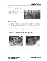
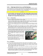
Check the shaft seal area of the spindle shaft surface on which a mechanical seal assembly is
installed. If any flaw is observed, resurface and finish with sandpaper.
c)
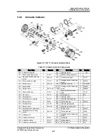
When you disassemble following each part, replace them with new ones, i.e. a speed increaser
drive gear side bearing [183], a roller bearing [185] including inner race and outer race, and a thrust
bearing [189].

