2202L5JE-DA-C5-N_2015.05.
5 Maintenance and Inspection
Compound 2-stage Screw Compressor
5.4 Disassembly and Inspection
1612LSC Speed Increaser Type
5-41
5.4.18 Low-stage
Unloader
Slide Valve and Guide Block
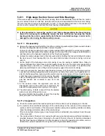
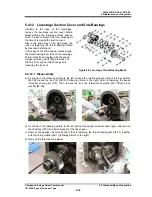
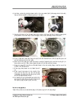
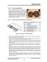
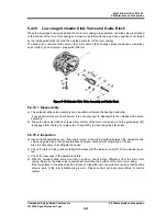
When the low-stage bearing head and the main rotor casing are separated, the slide valve is attached
to the bottom of the main rotor casing and moves in parallel with the axis whose position is controlled
by the inside guide block [87] and the outside perimeter (of the rotor casing).
The slide valve consists of slide valve 1 [54], slide valve 2 [55], hexagon socket head cap screws [58],
push rod [67], and oil injection pipe guide [168] etc.
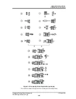
Figure 5-12 Unloader Slide Valve Assembly and Guide Block
5.4.18.1 Disassembly
a) The unloader slide valve assembly can be pulled out toward the bearing head side.
If any abnormalities are not observed, it is not necessary to disassemble the unloader slide valve
assembly.
b) The guide block stem [88] is screwed from bottom of the main rotor casing, and the guide block [87]
is engaged from the top. To replace two O-rings [89], remove the guide block stem.
5.4.18.2 Inspection
a) Inspect for abnormalities (e.g., flaw and/or wear) in the sliding surface between the unloader slide
valve and guide block. If any abnormalities observed, finish up with whetstone or the like.
Also it is necessary to investigate the cause.
b) Check for defect in the guide pin [68] which mates with the indicator cam [77] of the unloader push
rod.
c) Check for looseness in the assembled state.
d) With the unloader slide valve mounted in position, check a step difference from the main rotor
casing. Normally, the slide valve is positioned lower than the surface of the main rotor casing.
If the top surface of the slide valve has a trace of hitting the rotor, the probable cause is that the slide
valve is worn or the rotor shaft/bearing is worn. Please contact our local sales offices or service
centers.

