2202L5JE-DA-C5-N_2015.05.
5 Maintenance and Inspection
Compound 2-stage Screw Compressor
5.5
Reassembly
1612LSC Speed Increaser Type
5-44
5.5.1 Low-stage Unloader Slide Valve and Guide Block
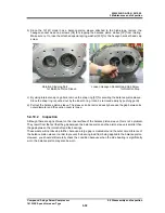
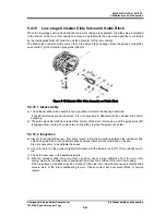
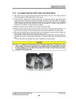
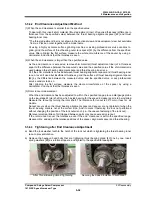
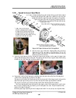
a) First, tightly screw the guide block stem [88] into the bottom of the main rotor casing, and then
mount the guide block [87] inside the main rotor casing.
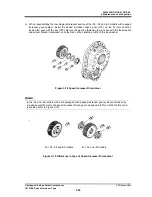
b) If the slide valve assembly has been disassembled, first make sure that the alignment position
between the slide valves [54] and [55] is accurately reproduced and then tighten the hexagon
socket head cap screws [58] with spring washers [267] at the specified torque. The outer diameter
of the spring washers used here is less than normal spring washers for hexagon socket head cap
screws. So, be careful not to mix up with other washers.
c)
Make sure to attach the O-ring [59] in the Oil injection pipe guide [168].
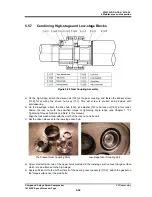
d) Gently smooth the outer surface of each part with a grindstone or sandpaper before attaching it to
the main rotor casing. Next, match the slide valve groove with the guide block and push gently.
d)
After assembly, hold and move the unloader push rod, and inspect its movement. Also, inspect the
seam between the part and the casing to ensure that it is even.
If it is not even, the part has not been assembled correctly and reassembly is necessary. Using it in
that state can lead to an unforeseen accident due to the outer surface of the rotor hitting the slide
valve.
* : It is not a problem if the unloader slide valve is slightly lower than the casing.
There is a problem with assembly if the unloader slide valve is higher than the
rotor casing. In that case, reassembly is essential. Using it in that state can lead
to heavy damage or an accident due to the outer surface of the rotor coming into
contact with the slide valve.
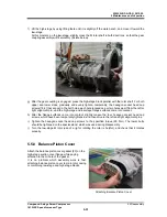
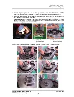
Guide Block Stem Inside Main Rotor Casing

