2202B0JE-DA-J-N_2012.01.
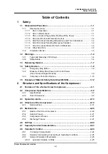
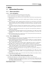
Table of Contents
Screw Compressor J-series
xiii
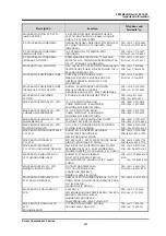
5.3.2 Replacement
Interval
for Refrigerant Oil ........................................................ 5-17
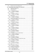
5.4 Disassembly and Assembly of the Compressor..................................... 5-18
5.4.1 Preparation
for
Disassembly .......................................................................... 5-18
5.4.2 Common
Work Items ...................................................................................... 5-20
5.4.3 Vi
Position Sensor .......................................................................................... 5-22
5.4.3.1 Precautions
for Removal ........................................................................... 5-23
5.4.3.2 Precautions
for Installation ........................................................................ 5-23
5.4.4 Seal
Cover ...................................................................................................... 5-24
5.4.4.1 Precautions
for Removal ........................................................................... 5-26
5.4.4.2 Precautions
for Installation ........................................................................ 5-26
5.4.5 Bearing
Cover................................................................................................. 5-28
5.4.5.1 Precautions
for Removal ........................................................................... 5-29
5.4.5.2 Precautions
for Installation ........................................................................ 5-30
5.4.6 Unloader
Indicator/Capacity Control Solenoid Valve ..................................... 5-32
5.4.6.1 Precautions
for Removal ........................................................................... 5-34
5.4.6.2 Precautions
for Installation ........................................................................ 5-34
5.4.7 Unloader
Cover............................................................................................... 5-35
5.4.7.1 Precautions
for Removal ........................................................................... 5-37
5.4.7.2 Precautions
for Installation ........................................................................ 5-38
5.4.8 Unloader
Cylinder ........................................................................................... 5-40
5.4.8.1 Precautions
for Removal ........................................................................... 5-41
5.4.8.2 Precautions
for Installation ........................................................................ 5-41
5.4.9 Vi
Cylinder ...................................................................................................... 5-43
5.4.9.1 Precautions
for Removal ........................................................................... 5-45
5.4.9.2 Precautions
for Installation ........................................................................ 5-45
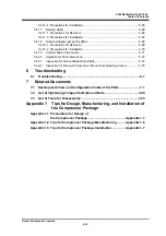
5.4.10 Balance
Piston Cover ..................................................................................... 5-46
5.4.10.1 Precautions for Removal ........................................................................... 5-46
5.4.10.2 Precautions for Installation ........................................................................ 5-47
5.4.11 Suction Cover ................................................................................................. 5-48
5.4.11.1 Preparation for Suction Adapter Removal ................................................. 5-50
5.4.11.2 Precautions for Removal ........................................................................... 5-50
5.4.11.3 Precautions for Installation ........................................................................ 5-50
5.4.12 Bearing Head.................................................................................................. 5-52
5.4.12.1 Precautions for Removal ........................................................................... 5-53
5.4.12.2 Precautions for Installation ........................................................................ 5-54
5.4.13
Separation of Suction Cover and Main Rotor Casing..................................... 5-56
5.4.13.1 Precautions for Removal ........................................................................... 5-57
5.4.13.2 Precautions for Installation ........................................................................ 5-57
5.4.14 Suction Cover ................................................................................................. 5-58
5.4.14.1 Precautions for Removal ........................................................................... 5-58
5.4.14.2 Precautions for Installation ........................................................................ 5-59
5.4.15 Rotor ............................................................................................................... 5-60
5.4.15.1 Precautions for Removal ........................................................................... 5-61
5.4.15.2 Precautions for Installation ........................................................................ 5-62
5.4.16 Separation
from Bearing Head ....................................................................... 5-64
5.4.16.1 Precautions for Removal ........................................................................... 5-64
5.4.16.2 Lifting of Bearing Head .............................................................................. 5-64
5.4.16.3 Lifting of Main Rotor Casing ...................................................................... 5-65
Summary of Contents for 170JL-V
Page 2: ......

