2200LZJE-HO-C6-N_2013.12.
Chapter 5 Maintenance
Compound 2-stage Screw Compressor 2016**C
5.7 Reassembly
5-62
5.7.13 Unloader Cylinder Cover
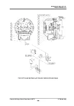
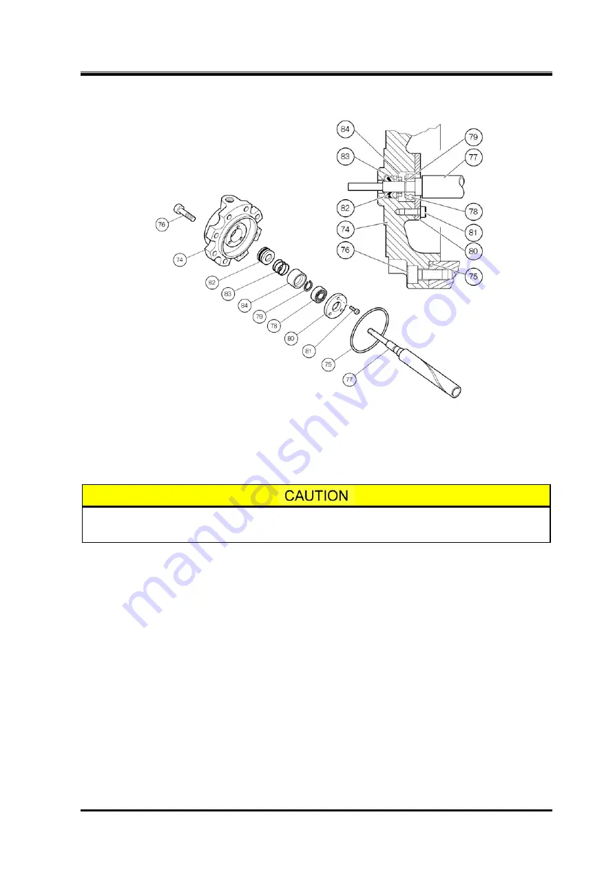
Figure 5-15 Development View of Unloader Cylinder Cover
a) Attach eye bolts to the unloader piston, and move it back and forth. Check once again that it
functions properly. During this manual check, pay attention not to let the piston reach the utmost
front position.
With some model (2016MSC), the slide valve may come off the guide block if you
pull the unloader piston excessively toward you.
b) Attach the ball bearing
【
78
】
to the shaft of the indicator cam
【
77
】
. When fitting, push the inner
ring of the bearing. Pushing the outer ring may damage the bearing.
Push the bearing to the stepped portion of the indicator cam and retain the bearing with the stop
ring.
c) Apply sufficient oil to the unloader cylinder cover
【
74
】
, and attach the V-ring set
【
82
】
. One of the
V-rings in a set is made of rubber (dark color) to improve sealing performance. As shown in Figure
5-15, it is set at the second position viewed from the outer side of the machine.
Set the V-ring in such a way that its ridge faces the machine's outer side and the lip faces the inner
side.
d) Install the spring
【
83
】
and spring retainer
【
84
】
into position. Then insert the shaft of the indicator
cam, which has been assembled in step b) above, into the V-ring. Fasten the bearing to the
unloader cylinder cover by using the bearing gland
【
80
】
.
e) After making sure that the indicator cam rotates smoothly, attach the O-ring
【
75
】
to the unloader
cylinder cover.
f) Attach the unloader cylinder cover to the unloader cylinder
【
60
】
. Push the unloader cylinder cover
in such a way that the guide pin
【
68
】
of the unloader push rod
【
67
】
just fits to the spiral groove of
the indicator cam. Secure the unloader cylinder cover with the hexagon socket head cap screws
【
76
】
, with its hole for supplying unloader working oil facing upward.


