2200LZJE-HO-C6-N_2013.12.
Chapter 5 Maintenance
Compound 2-stage Screw Compressor 2016**C
5.4 Compressor Disassembly Preparation
5-11
5.4.5 Removing and Lifting the Compressor
Do not allow anyone other than qualified personnel to lift and carry the
compressor. Entrusting the work to unqualified personnel may result in fall
accident.
Be sure not to assemble/disassemble the compressor while it is being lifted.
There is a risk that the compressor's main body or parts may drop on human
body.
The suction piping is located immediately above the compressor. Hold the piping or remove it in part,
so that the compressor lifting work is not hindered.
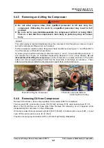
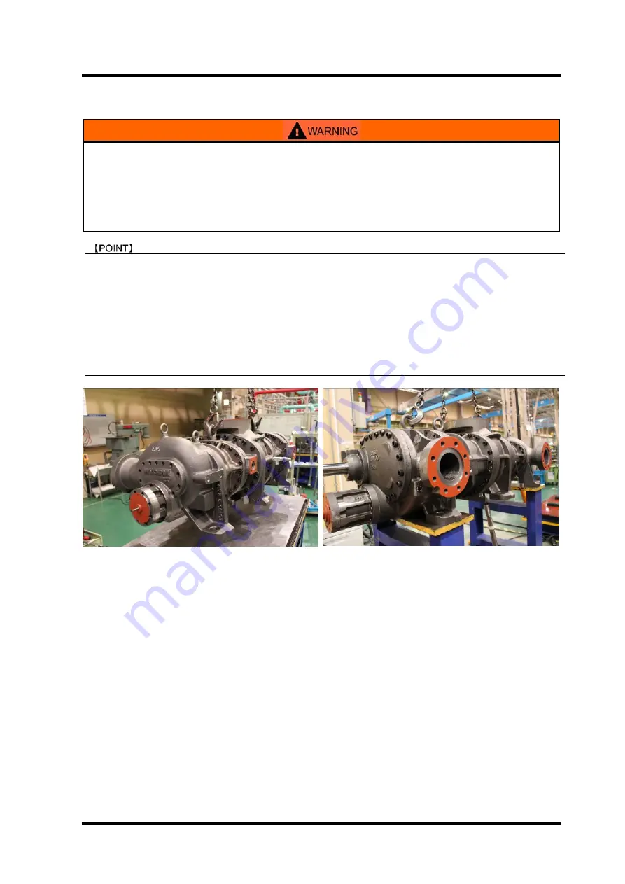
For the compressor locations where lifting tools should be attached, see Figure 3-1 and Photo 002 in
3.3 of this manual, or Photo 003 shown below.
If you are going to perform work step(s) other than steps
⑩
and
⑪
when performing work steps
⑤
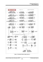
and onwards (see "Figure 5-1 Illustrated Disassembly Sequence" in 5.5 of this chapter),
do not
disassemble while lifting the compressor
, put the compressor on a table as shown in Photo 004
below, and remove approximately 8 bolts from the lower side of the flange as necessary. These
bolts cannot be removed after the compressor is brought down on the work bench.
Photo 003 Lifting the Compressor Photo 004 Lower-side Bolts for
Fastening Rotor Casing
5.4.6 Removing Oil from Compressor
Remove oil in advance, since a large quantity of oil remains inside the compressor.
There is plug
【
10
】
under suction covers
【
5-1
】
【
5-2
】
and plug
【
15
】
under bearing head
【
11-1
】
.
Most of the oil will flow out of these plug holes. Remove the remaining oil as it appears, while
disassembling the compressor on the surface plate.
Oil mainly resides inside a) unloader cylinders
【
60-1
】
【
60-2
】
, b) balance piston cover
【
22
】
, c) seal
cover
【
51
】
and d) suction covers
【
5-1
】
【
5-2
】
.
Prepare a receiving tray and waste cloth for oil that will spill during disassembly.

