2200LZJE-HO-C6-N_2013.12.
Chapter 5 Maintenance
Compound 2-stage Screw Compressor 2016**C
5.6 Overhaul
5-25
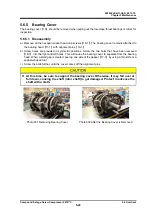
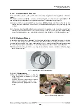
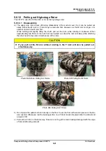
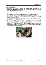
Photo 033 Separating High-Stage
and Low-Stage
5.6.6 Separating High-stage and Low-stage
Separate the high-stage and low-stage when pulling
out the high-stage thrust bearings or rotors of each
stage.
Structurally, they can be separated at the initial step of
disassembly.
5.6.6.1 Disassembly
a) As explained under
at 5.4.5 in this manual,
put the compressor on a special table and remove
the bolts from the lower side. Then, remove the
remaining hexagon socket head cap screws
【
18-2
】
.
At this moment, the upper side of the compressor is spaced apart the surface plate.
Brace the upper side with a rectangular piece of wood or the like to prevent it from falling when
disassembled.
As the screws
【
18-2
】
of the 2016**C model are 5 mm longer than other screws, they cannot be
used for other purposes. Distinguish these from others.
b) Drive alignment pins
【
19-2
】
into suction cover
【
5-1
】
.
c) The bearing head
【
11-2
】
and suction cover are stuck together by gasket
【
17-2
】
. Tap the suction
cover at its leg portion or screw in screws
【
18-2
】
(which have been removed) into the holes on the
bearing head, to separate the suction cover evenly by pushing.
Do not drive a screwdriver or chisel into the gap.
d) The power transmission gear couplings
【
151 to 161
】
are attached to the inside of M rotor shaft.
Move the main body in parallel with the shaft to separate the drive side and the driven side in the
direction of the shaft.
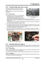
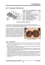
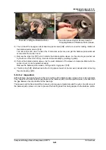
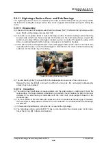
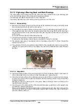
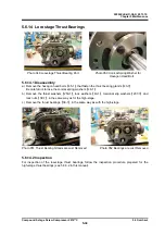
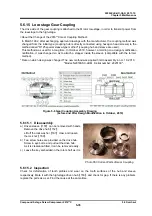
Photo 034 Low-stage After Separation Photo 035 Removing the Driven Hub
5.6.7 High-stage Side Gear Coupling
As known by seeing the parts/components separated in the previous chapter, the coupling as a power
transmission part is separated into the high-stage side and low-stage side, each one of which is fixed to
each shaft (rotor shaft).
5.6.7.1 Disassembly
Loosen the set screw
【
159
】
of the key attached to the driven hub
【
153
】
, and then remove the driven
hub. As it is clearance-fitted, it can be removed easily.
The set screw
【
159
】
should be with looseness stop and tooth to set firmly for the sure loothness stop.
5.6.7.2 Inspection
Check for abnormal deformation and/or wear on the tooth profiles and tooth surfaces. If there is any of
such defect, find the cause and replace the part.

