2200LZJE-HO-C6-N_2013.12.
Chapter 5 Maintenance
Compound 2-stage Screw Compressor 2016**C
5.6 Overhaul
5-28
5.6.9 Balance Piston Cover
Disassemble this part when pulling out the rotor or when inspecting the side bearing
【
28-2
】
or balance
piston.
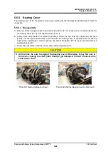
The balance piston cover
【
22
】
is removed, combined together with the unloader cylinder
【
60-2
】
. If
the unloader cylinder is pulled out and disassembled further, follow the procedure below.
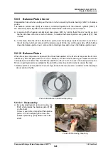
a) Loosen all of the hexagon socket head cap screws
【
24
】
by turning them three or four times, and
tap the side face of the cover with a hammer, to release the balance piston cover gasket
【
23
】
that
is stuck.
b) In this state, drain the oil from the balance piston and side bearings inside the suction cover. When
the oil has been drained, remove all the screws except for the one on the upper side. While holding
down the balance piston cover, remove the remaining screw and remove the balance piston cover.
5.6.10 Balance Piston
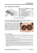
When the screw compressor is operated, the thrust load applied to the M rotor is large and the M rotor
rotates very fast compared with the F rotor. Therefore, the life of thrust bearing on the M rotor would
normally be much shorter than that of those attached on the F rotor. To reduce the bearing load on the
M rotor, a hydraulic piston is installed at the end of the rotor drive shaft in order to cancel the load.
* Balance piston is not required on the low-stage, because the low pressure conditions on the low-stage
do not shorten the life.
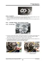
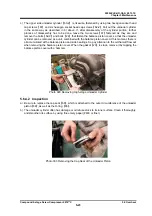
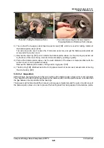
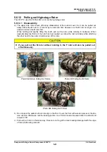
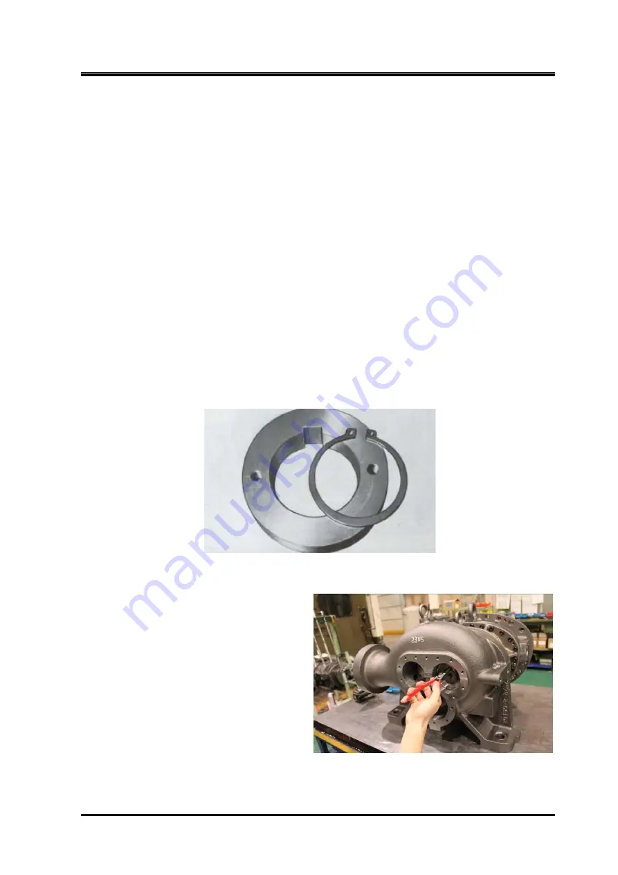
Photo 039 Balance Piston and Stop Ring
5.6.10.1 Disassembly
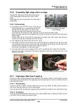
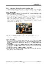
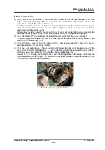
a) By using stopring plier, remove the stop ring
【
32
】
which retains the balance piston
【
30
】
on the shaft.
Screw in eye bolts, and pull out the balance
piston. It is not necessary to remove the
balance piston key
【
31
】
fitted in the rotor
shaft.
Photo 040 Removing Stop Ring

