2200LZJE-HO-C6-N_2013.12.
Chapter 5 Maintenance
Compound 2-stage Screw Compressor 2016**C
5.6 Overhaul
5-29
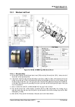
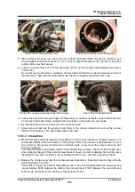
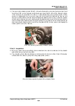
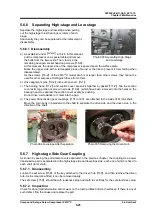
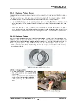
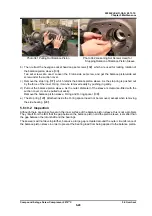
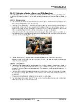
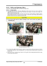
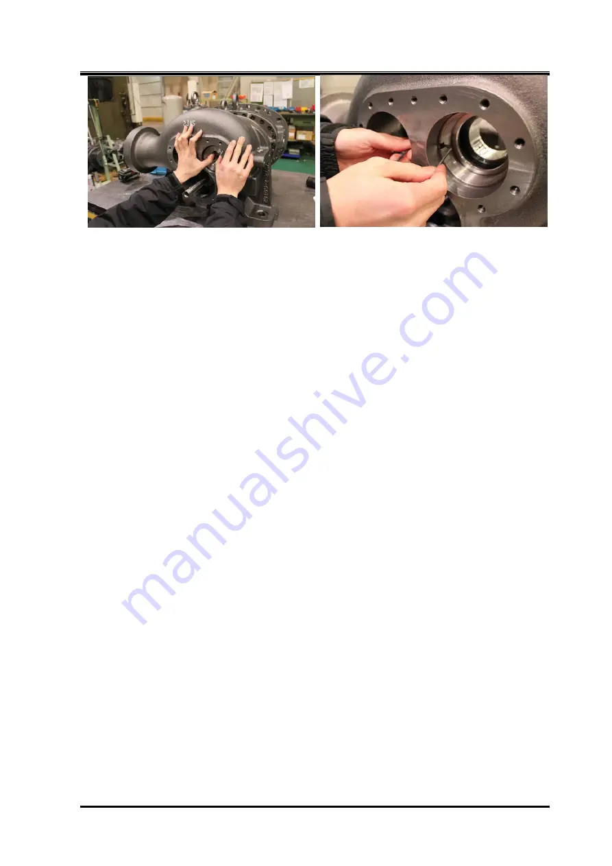
Photo 041 Pulling Out Balance Piston Photo 042 Loosening Set Screws Used for
Stopping Rotation of Balance Piston Sleeve
b) Then, retract the hexagon socket head cap set screws
【
34
】
which are used for locking rotation of
the balance piston sleeve
【
33
】
.
Two set screws are used. Loosen the F rotor-side set screw, and get the balance piston-side set
screw under the suction cover.
c) Remove the stop ring
【
37
】
which retains the balance piston sleeve. As the stop ring is pushed out
by the force of the inner O-ring, it can be removed easily by pushing in gently.
d) Pull out the balance piston sleeve. As the outer diameter of the sleeve is clearance-fitted with the
suction cover, it can be pulled out easily.
Remove the balance piston sleeve, O-ring and O-ring spacer
【
36
】
.
e) The stop ring
【
29
】
attached inside the O-ring spacer need not be removed, except when removing
the side bearing
【
28
】
.
5.6.10.2 Inspection
Although there are signs of wear on the inner surface of the balance piston sleeve, this is not a problem.
They result from the fact that the gap between the balance piston and the piston sleeve is smaller than
the gap between the rotor shaft and the bearings.
These wears will not develop further, because a large gap is created around the outer circumference of
the balance piston sleeve in order to prevent the bearing load from being applied to the balance piston.

