2200LZJE-HO-C6-N_2013.12.
Chapter 5 Maintenance
Compound 2-stage Screw Compressor 2016**C
5.6 Overhaul
5-38
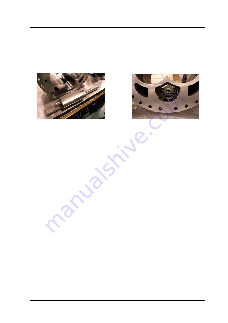
5.6.19 Low-stage Unloader Slide Valve and Guide Block
When the bearing head and rotor casing are separated, you will find that the slide valve is attached to
the lower area of the rotor casing. The valve moves in parallel with the axis, position-controlled by the
guide block
【
87-1
】
attached inside and by the outer circumference.
The slide valve consists of slide valve [1]
【
54-1
】
, slide valve [2]
【
55-1
】
, hexagon socket head cap
screw
【
58-1
】
, push rod
【
67-1
】
, oil injection pipe guide
【
168
】
, etc.
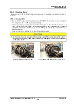
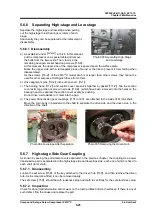
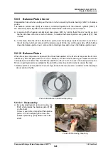
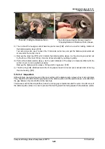
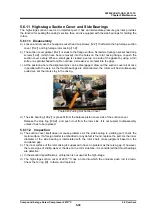
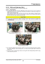
Photo 058 Unloader Slide Valve Photo 059 Unloader Slide Valve and Guide Block
5.6.19.1 Disassembly
a) If pulled in the discharge direction, the push rod
【
67-1
】
can be removed easily.
b) When replacing the push rod, remove the hexagon socket head cap screw
【
162
】
.
c) The oil injection pipe guide
【
168
】
is fastened from inside by using lock nut. Pull out the hexagon
socket head cap screws
【
58-1
】
and washers
【
267-1
】
to disassemble the slide valve assembly,
so remove the guide.
5.6.19.2 Inspection
a) Check the gap between the guide block and the sliding surface of the slide valve guide.
b) Check for defects in the grooved pin (dowel pin) at the tip end of the push rod
【
67-1
】
which
engages with indicator cam
【
77-1
】
.
c) Check for looseness in the assembled state.
d) Thoroughly check the hole into which the oil injection pipe is inserted.

