2200LZJE-HO-C6-N_2013.12.
Chapter 5 Maintenance
Compound 2-stage Screw Compressor 2016**C
5.7 Reassembly
5-41
5.7.1 Low-stage Unloader Slide Valve and Guide Block
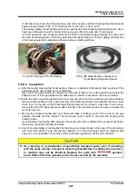
a) First, tightly screw the guide block stem
【
88-1
】
into the bottom of the casing, and then mount the
guide block
【
87-1
】
inside the casing.
b) When the slide valve assembly has been disassembled, tighten the hexagon socket head cap
screws
【
58-1
】
to their specified torque (50 N·m) so that the joints are aligned correctly.
c) Smoothen the outer periphery of the assembly by using a grinding stone or emery paper, and then
attach the assembly to the casing. Next, align the guide block with the slide valve groove, and push
in gently.
d) After assembly, hold the unloader push rod and move it several times to check its movement.
Inspect the joint with the casing, and confirm that there is no unevenness.
Since unevenness indicates improper assembly, reassemble it again. If used without correcting it,
the outer periphery of the rotor may hit against the slide valve, causing an unexpected accident.
* Regarding the unevenness between the unloader slide valve and the casing, there is no problem if
the slide valve is slightly lower than the casing.
If the unloader slide valve is higher than the rotor casing, there is a problem in
assembly. Do not leave the problem as it is. Be sure to reassemble. If used
without correcting it, the outer periphery of the rotor may hit against the slide
valve, which will cause a severe damage accident.
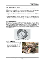
Photo 060 Guide Block Stem Inside the Casing Photo 061 High-stage Rotor Casing
5.7.2 High-stage Rotor Casing
For the 2016**C model, deal it in the same way as with the low-stage.

