2200LZJE-HO-C6-N_2013.12.
Chapter 5 Maintenance
Compound 2-stage Screw Compressor 2016**C
5.7 Reassembly
5-43
5.7.4 Bearing Head and Rotor Casing (High/Low-stage)
As the bearing head gasket is not formed symmetric laterally, pay attention to the
installation direction. If it is not oriented correctly, the oil route provided in the
casing may be blocked.
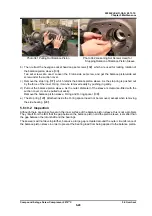
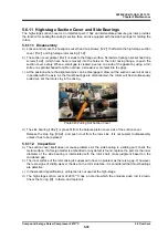
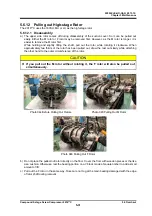
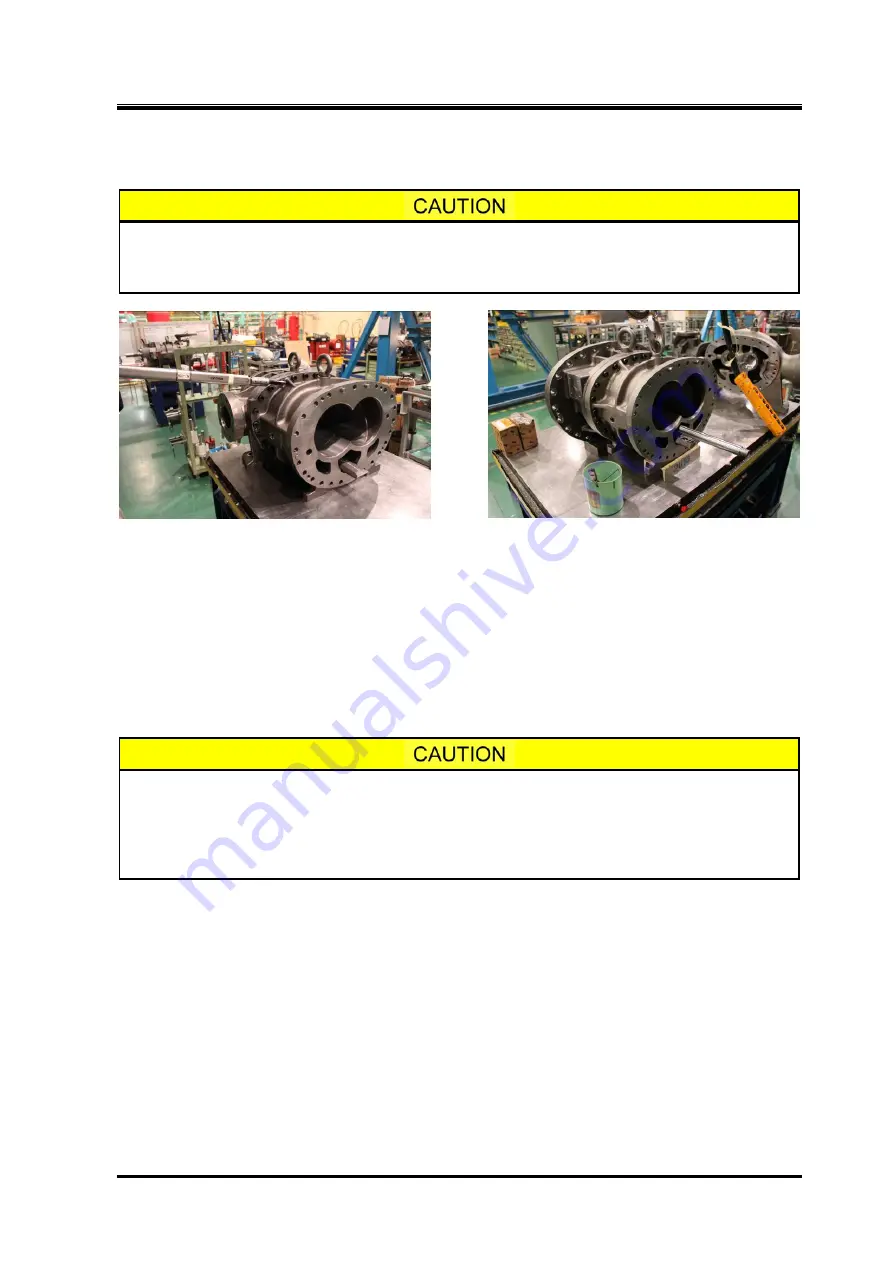
Photo 064 Fastening Low-stage Assembly with Bolts Photo 065 High-stage Assembly
a) Fit the unloader push rod in the hole of bearing head. Then, slide the bearing head or rotor casing to
let them mate together.
b) Loosely tighten two bolts. Next, drive in the alignment pins
【
3-1
】
to fix the position, and then screw
bolts in opposing positions, and then fasten the bolts evenly in turn.
c) After fastening the bolts, check that the bearing head gasket is not protruding toward the inside of
the casing. New gaskets always protrude toward the inside of the casing. Cut the protruded portion
with a sharp knife.
d) Assemble the high-stage side in the same way.
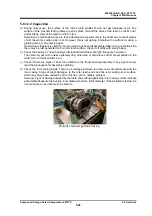
After attaching the bearing head and the rotor casing, be sure to check whether
the bearing head gasket is protruded. If you omit this check, the gasket could be
caught between the rotor end face and the bearing head surface, preventing to
obtain accurate measurement values. If you adjust the end clearance under this
condition and operate the system, the performance may be deteriorated.

